Process and equipment for recycling waste engine oil

A technology of waste oil and reuse, applied in the direction of lubricating compositions, etc., can solve the problems of tower blockage, high viscosity and short operating cycle.

Inactive Publication Date: 2018-04-06
盘锦阳光节能环保科技有限公司
View PDF3 Cites 8 Cited by
  • Summary
  • Abstract
  • Description
  • Claims
  • Application Information

AI Technical Summary

Problems solved by technology

Nirvana has high viscosity, floats in the oil, is not easy to separate, and the tower is seriously blocked. In addition, impurities such as sludge, iron filings, soot and other impurities in the waste oil make the furnace and tower blocked by the atmospheric and vacuum distillation

Method used


Image

  • Process and equipment for recycling waste engine oil
  • Process and equipment for recycling waste engine oil
  • Process and equipment for recycling waste engine oil

Examples


Embodiment 1

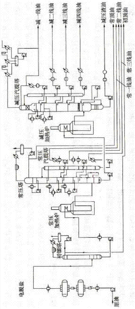
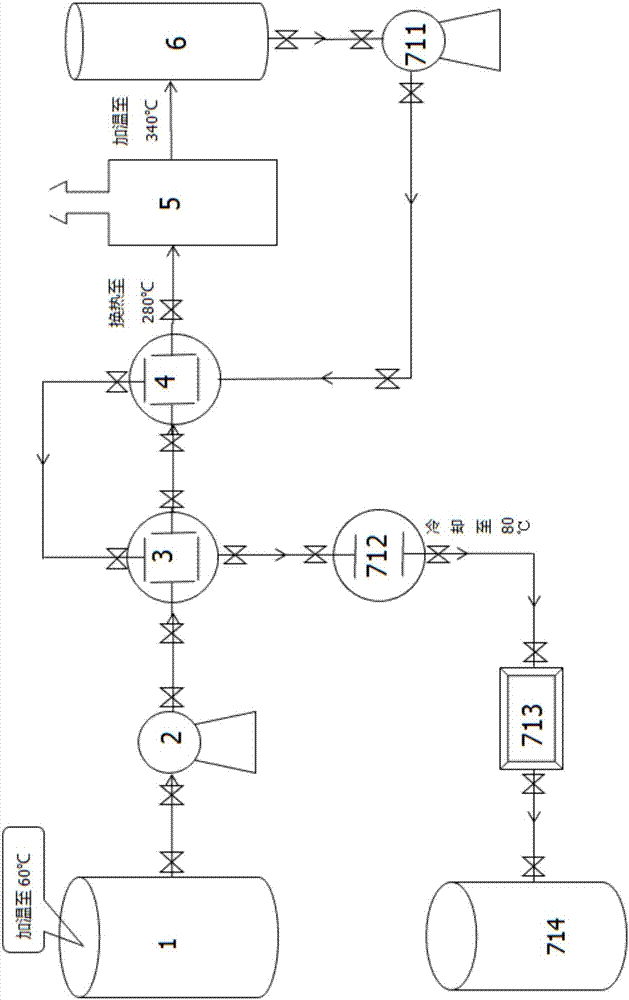
[0037] A process for recovering and reusing waste engine oil, comprising an atmospheric and vacuum distillation process, the atmospheric and vacuum distillation process including electric desalination, initial distillation, atmospheric distillation and vacuum distillation, and also including The pretreatment process, the pretreatment process includes the following steps: as figure 2 As shown, the waste engine oil is heated to 60°C in the storage tank 1, then heated to 280°C by the crude oil pump 2 to the first heat exchanger 3, then to the second heat exchanger 4, and then heated to 280°C by the vertical tubular heating furnace 5. 330-350°C, enter the flash tower 6, the bottom material of the flash tower is sent to the second heat exchanger 4 through the tower bottom pump 711, passes through the first heat exchanger 3, and then is cooled to 70-90°C by the water cooler 712 , filter out impurities through filter 713 to obtain raw material oil.

[0038] Preferably, it is heated...

Embodiment 2

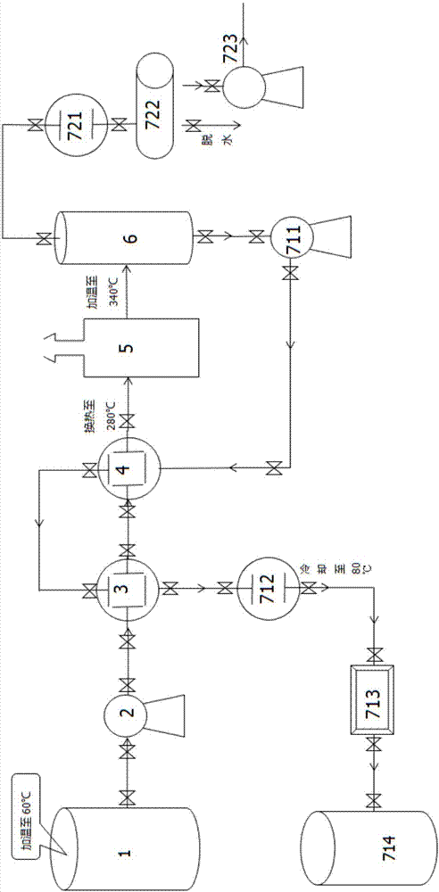
[0043] The difference from Example 1 is that, as image 3 As shown, it also includes that the overhead material of the flash tower passes through the third heat exchanger 721 to the overhead fractionation tank 722 to obtain dehydrated and light component-removed oil products.

[0044]The waste engine oil recovery and reuse process in this embodiment also includes a recovery and utilization device for the tower top gas. The mixed gas of gasoline and diesel components is evaporated from the top of the flash tower, and after recovery, it is cooled, exported, separated, stored and transported, and then sold. This is another income product of waste engine oil recycling and reuse.

Embodiment 3

[0046] A waste engine oil recovery and reuse equipment, including atmospheric and vacuum distillation equipment, also includes pre-processing equipment, the pre-processing equipment includes: a storage tank 1, a crude oil pump 2, a first heat exchanger 3, a second heat exchanger 4. Vertical tubular heating furnace 5, flash tower 6, second heat exchanger 4, water cooler 712, filter 713, finished product tank 714, connecting pipes and valves.


PUM


Abstract

The invention discloses a process for recycling waste engine oil. The process comprises an atmospheric and vacuum distillation process including electro-desalting, forerunning, atmospheric distillation and vacuum distillation, and further comprises a pretreatment process prior to the atmospheric and vacuum distillation process. The process comprises the following steps: S1, heating the waste engine oil to the temperature of 330-350 DEG C to obtain a liquid mixture and a gas mixture; and S2, cooling the liquid mixture obtained from step S1 to the temperature of 70-90 DEG C and then filtering the liquid mixture. By the process for recycling the waste engine oil, the problems that by an existing atmospheric and vacuum distillation method, alunite is produced from water, impurities, scrap ironand various additives in waste engine oil at high temperature, and then, furnace blockage and tower blockage are caused during processing are solved, the problems that the longest running period of the existing atmospheric and vacuum distillation method is about thirty days, then a tower requires to be cleaned, a large number of labors and financial resources are wasted, and worst of all, production requires to stop during cleaning of the tower are also solved, and continuous running can be implemented.

Description

technical field [0001] The invention belongs to the field of lubricant recovery, and in particular relates to a process and equipment for recovery and reuse of waste engine oil. Background technique [0002] Lubricating oil is a necessary petroleum product for all kinds of machinery. It is used on various types of automobiles and mechanical equipment to lubricate machinery, reduce mechanical friction, make machinery run at high speed and for a long period, and protect the liquid or semi-solid of machinery and processed parts. Lubricants mainly play the roles of lubrication, auxiliary cooling, rust prevention, cleaning, sealing and buffering. It is the soul of mechanical technology. Today's modern society would not exist without high-quality lubricating oils that meet mechanical requirements. [0003] Waste lubricating oil is the dirty oil produced after the use of various machinery. Especially in today's society, the number of automobiles is very large, and a large amount ...

Claims


Application Information

Patent Timeline
IPC IPC(8): C10M175/00
CPCC10M175/00C10M175/0025C10M175/0033
Inventor 刘勇
Owner 盘锦阳光节能环保科技有限公司
Why Eureka
Try Eureka