
Combustion device of circuit cyclone pre-mixing multi-row array jet cyclone penetrating heat accumulating sleeve

A combustion device and array technology, which is applied to the combustion of solid fuel, burner, combustion method, etc., can solve the problems of poor staging combustion effect of gas, low mixing intensity, uneven mixing of combustion-supporting air and gas, etc.

Active Publication Date: 2018-04-10
郑州釜鼎热能技术有限公司
View PDF8 Cites 5 Cited by
  • Summary
  • Abstract
  • Description
  • Claims
  • Application Information

AI Technical Summary

Problems solved by technology

[0003] Based on the development and application of the above-mentioned staged combustion technology and flue gas recirculation combustion technology, and the gradual popularization and application of the heat storage body combustion technology, the present invention proposes a ring swirl premixed multi-row array jet swirl penetrating heat storage sleeve The advanced combustion device can effectively solve various problems such as uneven mixing of combustion-supporting air and gas, low mixing intensity, poor and uncontrollable gas staged combustion effect, difficulty in uniform distribution of air flow field, and uncontrollable combustion temperature.

Method used


Image

  • Combustion device of circuit cyclone pre-mixing multi-row array jet cyclone penetrating heat accumulating sleeve
  • Combustion device of circuit cyclone pre-mixing multi-row array jet cyclone penetrating heat accumulating sleeve

Examples


Embodiment Construction

[0008] The specific implementation manners of the present invention will be described in detail below in conjunction with the accompanying drawings.

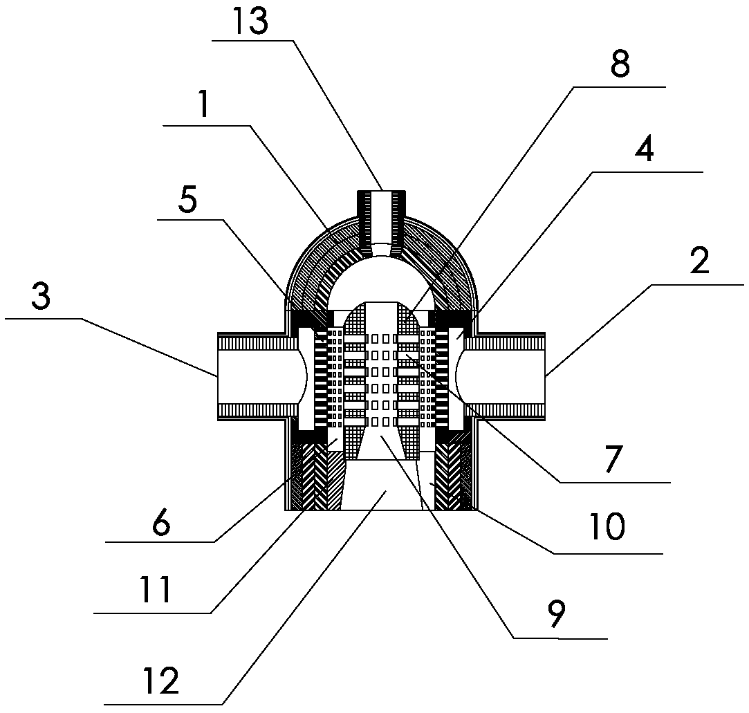
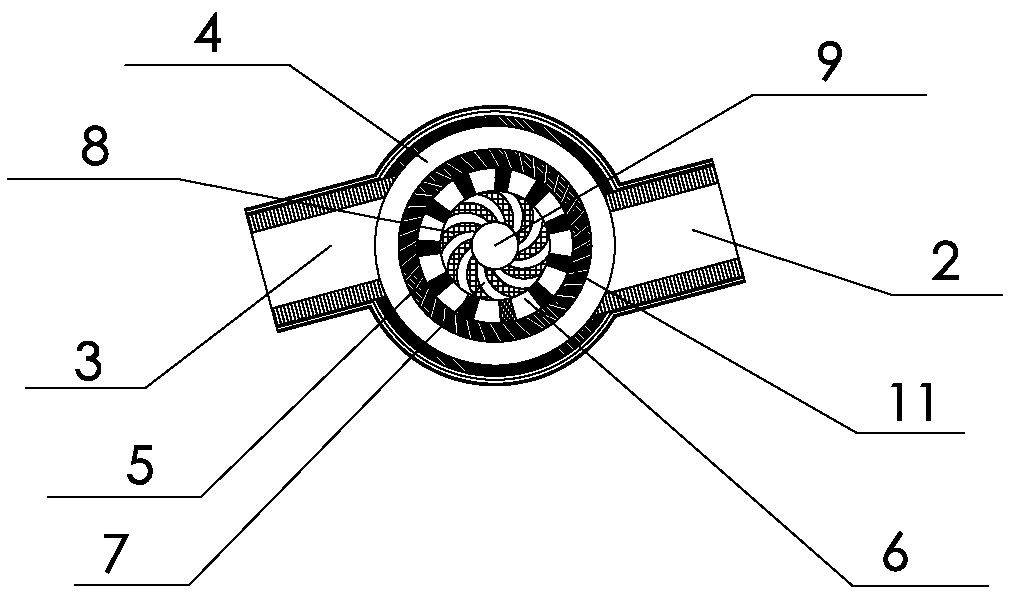
[0009] Such as Figure 1-Figure 2 As shown, the present invention includes a burner wall 1, a swirl premixing ring 4, a swirl array premixed nozzle 5, a premixed swirl combustion ring 6, a cylindrical combustion-supporting heat storage body 8, and a swirl array combustion Nozzle 7, high-speed swirling channel 9, regulating airflow injection inlet pipe 13, air inlet pipe 3, gas inlet pipe 2 and combustion smoke outlet 12, the burner wall 1 is the upper hemispherical vault and the lower cylindrical wall The inner cavity of the wall of the burner is the combustion chamber, the cylindrical wall is provided with a swirl pre-mixing ring 4, and the outer wall of the swirl pre-mixing ring is connected with a wall protruding from the cylindrical wall. Multiple pairs of gas inlet pipes 2 and air inlet pipes 3, each pair of gas inlet pipe...


PUM

PropertyMeasurementUnit
Slopeaaaaaaaaaa

Abstract

The invention relates to a combustion device of a circuit cyclone pre-mixing multi-row array jet cyclone penetrating heat accumulating sleeve and solves the problems that combustion air and coal gas are not uniformly mixed, the mixing strength is not high, the coal gas grading combustion effect is poor and uncontrollable, the air flow field distribution is hardly uniform, and the combustion temperature is uncontrollable effectively. Multiple pairs of coal gas inlet pipes and air inlet pipes are arranged on the outer side wall of a cyclone premixing circuit in a cylindrical wall body; multiplerows of cyclone array premixing gas nozzles are arranged in the inner side wall; a high speed cyclone channel is arranged in the barrel-shaped combustion heat accumulating body in an inner cavity; a premixed gas cyclone combustion circuit is arranged between the barrel-shaped combustion heat accumulating body and the cylindrical wall body; multiple rows of cyclone array combustion nozzles are arranged in the cylindrical wall; the spaces in the plurality of combustion heat accumulating body supporting columns in the bottom are combustion fuel gas outlets; and an adjusting air flow spraying inlet pipe is arranged on a semispherical arch crown. The combustion device changes the flow field structure of the combustion air flow, intervenes the combustion process deeply, is fuel- and investment-saving and reduces the emission of toxic gas.

Description

technical field [0001] The invention relates to an airflow regulating combustion equipment used in heat utilization equipment of industrial furnaces, in particular to a combustion device in which a circular swirl premixed multi-row array jet swirl penetrates a heat storage sleeve. Background technique [0002] At present, with the optimization of the process and the increasingly prominent environmental protection issues in industrial furnaces, higher requirements are put forward for the adjustable performance of the combustion process of the burner, that is, the combustion temperature can be effectively controlled under high-efficiency and high-intensity combustion conditions. Adjust the combustion load, and realize energy-saving and low-nitrogen efficient combustion. It is feasible and effective technical means to use regenerative body combustion technology, staged combustion technology, and flue gas backflow technology to improve mixed combustion state, adjust combustion i...

Claims


Application Information

Patent Timeline
IPC IPC(8): F23B80/02F23D14/02F23D14/46F23D14/58F23D14/62F23G7/06F23J15/06F28D20/00
CPCF23B80/02F23D14/02F23D14/46F23D14/58F23D14/62F23G7/06F23J15/06F28D20/00Y02E60/14
Inventor 陈维汉陈云鹤杨海涛张佳鹏
Owner 郑州釜鼎热能技术有限公司
Learn More