Defoaming marsh gas tank

A technology of biogas digesters and gas storage chambers, applied in the field of biogas, can solve the problems of low gas production rate, easy crusting of scum, and unfavorable stability and improvement of the combustion efficiency of pool-strength stoves, so as to increase gas production and facilitate full The effect of decomposition

Inactive Publication Date: 2018-04-13
CHENGDU JINHUI TECH
View PDF1 Cites 0 Cited by
  • Summary
  • Abstract
  • Description
  • Claims
  • Application Information

AI Technical Summary

Problems solved by technology

Although hydraulic biogas digesters have the above advantages, there are also many disadvantages: First, due to repeated changes in air pressure, this has a negative impact on the strength of the pool body and the stability and improvement of the combustion efficienc

Method used


Image

  • Defoaming marsh gas tank
  • Defoaming marsh gas tank

Examples


Embodiment 1

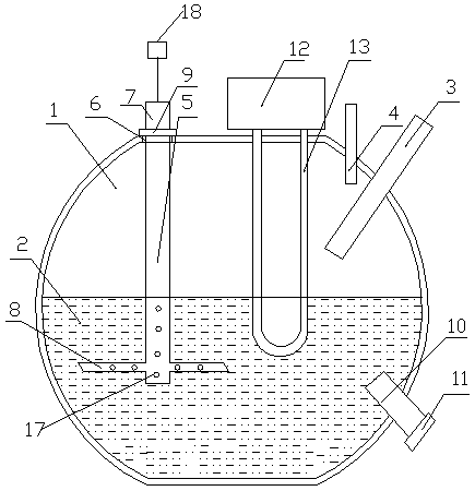
[0022] see figure 1 , a defoaming biogas digester, including a gas storage chamber 1 and a fermentation chamber 2, a feed pipe 3 and an air outlet pipe 4 communicating with the gas storage chamber 1, and a stirrer 5, and an annular hole 6 is opened on the outer wall of the gas storage chamber 1 , the stirring shaft 7 of the stirrer 5 stretches into the fermentation chamber 2 through the annular hole 6, and the stirring blade 8 positioned in the fermentation chamber 2 is arranged on the stirring shaft 7, and the stirring blade positioned outside the air storage chamber 1 A cover 9 is set on the shaft 7, and the diameter of the cover 9 is not less than the inner diameter of the annular hole 6. A discharge pipe 10 is arranged in the fermentation chamber 2, and a discharge cover 11 is provided at the outlet of the discharge pipe 10. The top of the gas storage chamber 1 is fixedly connected with a solar heat collector 12, and the solar heat collector 12 is connected with a heat col...

Embodiment 2

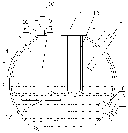
[0025] see figure 2, a defoaming biogas digester, including a gas storage chamber 1 and a fermentation chamber 2, a feed pipe 3 and an air outlet pipe 4 communicating with the gas storage chamber 1, and a stirrer 5, and an annular hole 6 is opened on the outer wall of the gas storage chamber 1 , the stirring shaft 7 of the stirrer 5 stretches into the fermentation chamber 2 through the annular hole 6, and the stirring blade 8 positioned in the fermentation chamber 2 is arranged on the stirring shaft 7, and the stirring blade positioned outside the air storage chamber 1 A cover 9 is set on the shaft 7, and the diameter of the cover 9 is not less than the inner diameter of the annular hole 6. A discharge pipe 10 is arranged in the fermentation chamber 2, and a discharge cover 11 is provided at the outlet of the discharge pipe 10. The top of the gas storage chamber 1 is fixedly connected with a solar heat collector 12, and the solar heat collector 12 is connected with a heat col...


PUM


Abstract

The invention discloses a defoaming biogas digester, which comprises a gas storage chamber and a fermentation chamber, and also includes a stirrer, an annular hole is opened on the outer wall of the gas storage chamber, and the stirring shaft of the stirrer extends into the fermentation chamber through the annular hole , the stirring shaft is provided with a stirring blade located in the fermentation chamber, a card cover is set on the stirring shaft located outside the gas storage chamber, a discharge pipe is provided in the fermentation chamber, and a discharge cover is provided at the outlet of the discharge pipe, The top of the air storage chamber is fixedly connected with a solar heat collector, and the solar heat collector is connected with a heat collection return pipe, the stirring shaft is a hollow stirring shaft, the stirring blade is a hollow stirring blade, the hollow stirring shaft and the hollow stirring The blades are provided with defoaming holes, and the top of the stirring shaft is connected with a vacuum defoamer. The present invention can maintain a good temperature in the fermentation chamber by arranging a solar heat collector, and the motor drives the paddles to rotate to generate a vortex, which can fully decompose the fermentation raw materials, thereby increasing the biogas output.

Description

technical field [0001] The invention relates to the technical field of biogas, in particular to a defoaming biogas digester. Background technique [0002] Biogas is a mixture of various gases, the main component of which is methane. People often say that biogas fermentation refers to the process in which biogas bacteria decompose organic matter and produce biogas. According to the role of various bacteria in the biogas fermentation process, biogas bacteria can be divided into two categories. The first type of bacteria is called decomposing bacteria, and its function is to decompose complex organic matter into simple organic matter and carbon dioxide. Among them, there are bacteria that specialize in decomposing cellulose, called cellulolytic bacteria; bacteria that specialize in breaking down protein, called proteolytic bacteria; bacteria that specialize in breaking down fat, called lipolytic bacteria; the second type of bacteria is called methane-containing bacteria, us...

Claims


Application Information

Patent Timeline
IPC IPC(8): C12M1/21C12M1/107C12M1/02C12M1/00
CPCC12M21/04C12M23/36C12M27/02C12M41/18
Inventor 张一帆
Owner CHENGDU JINHUI TECH
Why Eureka
Try Eureka