Desulfurization and low-temperature denitration system and process for clean flue gas emission

A low-temperature denitration and desulfurization system technology, applied in the field of desulfurization and low-temperature denitration systems, can solve the problems of high energy consumption and increase the resistance of flue gas, and achieve the effects of reducing emissions, high dust removal rate and wide application range.

Inactive Publication Date: 2018-04-17
北京亿玮坤节能科技有限公司
View PDF9 Cites 4 Cited by
  • Summary
  • Abstract
  • Description
  • Claims
  • Application Information

AI Technical Summary

Problems solved by technology

CN103406010B discloses a desulfurization, denitrification and dust removal device. This technology is a spray scattering tower. The desulfurization and dust removal effects can be significantly improved through this device, but the disadvantage of this technology is that the smoke resistance is increased and the energy consumption is relatively high.
CN205570079U discloses an integrated ultra-low emission system for desulfurization, denitrification, mercu

Method used


Image

  • Desulfurization and low-temperature denitration system and process for clean flue gas emission
  • Desulfurization and low-temperature denitration system and process for clean flue gas emission
  • Desulfurization and low-temperature denitration system and process for clean flue gas emission

Examples


Embodiment

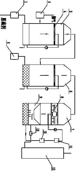
[0030] see figure 1 , the desulfurization and low-temperature denitrification system and process for clean flue gas discharge in the illustration are preferred embodiments of the present invention, including a desulfurization system, a denitrification system, a flue gas washing system and a flue gas discharge system. The desulfurization system consists of a desulfurization absorption tower, a desulfurization The denitrification system consists of a denitrification absorption tower, an ozone generator, etc. The flue gas washing system consists of a cooling scrubber and a washing water supply system, and the cooling scrubber is a water spray tower; the flue gas discharge system includes a chimney , the cleaned flue gas is finally discharged through the chimney.

[0031] In this example, flue gas desulfurization by magnesium method and denitrification by ozone oxidation method are adopted. The specific process is as follows:

[0032] After the purchased MgO powder is matured and...

example 1

[0048] Flue gas condition: 100000 Nm3 / h; SO 2 Concentration 800 mg / L; NO concentration 300mg / L; dust concentration 50 mg / L; boiler flue gas temperature: 120°C.

[0049] Measured after the steps of the foregoing examples:

[0050] The temperature after the absorption tower: 55°C and 43°C; the temperature after the low-temperature washing tower: 28°C;

[0051] SO after flue gas cleaning 2 Concentration 0.8mg / L; NO concentration 2.1mg / L; dust concentration 0.3mg / L.

[0052] Desulfurization efficiency: 99.8%; denitrification efficiency: 99.3%; dust removal efficiency: 99.8%


PUM


Abstract

The invention discloses a desulfurization and low-temperature denitration system for clean flue gas emission. The desulfurization and low-temperature denitration system comprises a desulfurization system, a denitration system, a flue gas washing system and a flue gas emission system, wherein the desulfurization system is composed of a desulfurizing absorption tower, a desulfurizing solution preparation system and a desulfurizing solution circulating system; the denitration system is composed of a denitrating absorption tower, an ozone generator and a denitrating solution circulating system; the flue gas washing system comprises a scrubbing tower and a scrubbing water supply system; the flue gas emission system is a chimney; and flue gas from a boiler is sequentially subjected to desulfurization, low-temperature denitration and flue gas scrubbing. The desulfurization and low-temperature denitration system disclosed by the invention has excellent desulfurization, denitration and dust removal effects and can eliminate a 'white smoke' problem caused by the flue gas. Moreover, the system disclosed by the invention solves the problem of secondary pollution in the desulfurization and denitration process and offers help for reducing and eliminating haze.

Description

technical field [0001] The invention relates to the technical field of flue gas desulfurization and denitrification, in particular to a desulfurization and low-temperature denitrification system and process for clean emission of flue gas. Background technique [0002] In recent years, with the development of economy and industry, more and more serious air pollution has seriously troubled people's lives. For this reason, the state has become more and more stringent in monitoring the discharge of industrial emissions, and the discharge standards have become more and more stringent. According to the relevant regulations on environmental protection, the emission concentration of SO2 should be lower than 100mg / m3, the emission concentration of dust particles should be lower than 30mg / m3, the emission concentration of nitrogen oxides should be lower than 100mg / m3, and the discharge of pollutants into the atmosphere must meet the standards. This requires a high degree of purificat...

Claims


Application Information

Patent Timeline
IPC IPC(8): B01D53/78B01D53/56B01D53/50
CPCB01D53/502B01D53/507B01D53/56B01D53/78
Inventor 刘森
Owner 北京亿玮坤节能科技有限公司
Why Eureka
Try Eureka