Cladding supermode interference based fiber reflective probe sensor and manufacturing method thereof

A reflective, sensor technology, applied in the direction of converting sensor output, using optical devices to transmit sensing components, instruments, etc., can solve the problems of being easily interfered by other external factors, very high manufacturing process requirements, and high processing technology requirements. Easy field detection, compact, easy-to-manufacture effects

Inactive Publication Date: 2018-04-17
TIANJIN UNIVERSITY OF TECHNOLOGY
View PDF10 Cites 1 Cited by
  • Summary
  • Abstract
  • Description
  • Claims
  • Application Information

AI Technical Summary

Problems solved by technology

These interferometers have some inherent disadvantages: the diameter of the tapered interferometer is very thin, the structure is relatively fragile and easy to break, and it is easily disturbed by other external factors; the "single-mode-multimode-single-mode" intermode interferometer In order to achieve a relatively high fringe contrast, it usually causes a large insertion loss; while the cascaded grating interferometer requires high processing technology, and it is usually difficult to process grating pairs with completely consistent physical parameters, so the repeatability of this type of interferometer low and difficult to manufacture
[0004] In addition, there is an intermode interferometer based on the F-P cavity. This type of cavity structure interferometer has very high requirements on the manufacturing process, which is not conducive to widespread industrial application.

Method used


Image

  • Cladding supermode interference based fiber reflective probe sensor and manufacturing method thereof
  • Cladding supermode interference based fiber reflective probe sensor and manufacturing method thereof
  • Cladding supermode interference based fiber reflective probe sensor and manufacturing method thereof

Examples


Embodiment Construction

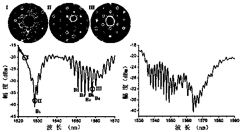
[0033] refer to figure 1 , figure 2 and image 3 , a method for manufacturing an optical fiber reflective probe sensor based on cladding supermode interference, comprising the following steps:

[0034] 1. Connect the two ends of the all-solid photonic bandgap fiber to the broadband light source and the spectrometer respectively through the single-mode fiber. The all-solid photonic bandgap fiber and the single-mode fiber are welded to the core to avoid interference effects. The wavelength range of the broadband light source needs to cover the wavelength range to be processed The wavelength variation range of the interferometer. Preferably, the single-mode fiber used in step (1) has a core diameter of 8.3 μm and a diameter of 125 μm, and the length of the all-solid photonic bandgap fiber used is greater than 10 mm. In the embodiment of the present invention, the all-solid photonic bandgap fiber used supports the core LP at the same time 01 mode with a high index column in t...


PUM


Abstract

A cladding supermode interference based fiber reflective probe sensor is composed of a single-mode fiber and a cut all-solid photon band-gap fiber, the end, close to the single-mode fiber, of the all-solid photon band-gap fiber is etched with a long-period grating, and the tail end of the all-solid photon band-gap fiber includes a reflection surface. A manufacturing method of the sensor comprisesthat 1) the two ends of the all-solid photon band-gap fiber are connected with a broadband light source and a spectrometer via single-mode fibers respectively; 2) one end of each single-mode fiber atone side of the all-solid photon band-gap fiber is fixed, the other end of the single-mode fiber is loaded with a counterweight, and the all-solid photon band-gap fiber is placed in a processing areaof a carbon dioxide laser marking machine; 3) output laser pulse energy of a high-energy carbon dioxide laser and the period and length of a processing grating are determined, and the grating is written; and 4) one end, far from the long-period grating, of the all-solid photon band-gap fiber is cut and serves as the reflecting surface. The sensor is high in reliability and contract and compact instructure, and can be used for the sensing field, especially for field measurement in the high-temperature environment.

Description

technical field [0001] The invention relates to the field of optical fiber sensing, in particular to an optical fiber reflection probe sensor based on cladding supermode interference and a manufacturing method thereof. Background technique [0002] Optical fiber intermode interferometer is an important type of optical device in the field of optical fiber. It can not only be used to manufacture important devices such as optical fiber filters, multi-wavelength lasers, and wavelength division multiplexers, but also has a very wide range of applications in the field of optical fiber sensing. The principle of fiber-optic intermode interferometer is to adopt specific mode excitation and coupling technology. Coupling and interference occur between the core fundamental mode and the core higher-order mode or cladding mode. When the external environment changes, it will cause the drift of the corresponding spectral interference peak, so that various external physical quantities includ...

Claims


Application Information

Patent Timeline
Patent Type & Authority Applications(China)
IPC IPC(8): G01D5/353G01D21/02
CPCG01D5/35316G01D21/02
Inventor 黄薇刘艳格王志游永程徐陈胜勇
Owner TIANJIN UNIVERSITY OF TECHNOLOGY
Why Eureka
Try Eureka