Self-resetting frame-shear wall structure for reinforcing earthquake-damaged frame and construction method

A shear wall and self-resetting technology, which is applied to walls, earthquake resistance, building components, etc., can solve problems such as structural damage and non-structural component damage, and achieve the effects of low earthquake damage, reduced earthquake-induced damage, and small damage

Active Publication Date: 2018-04-20
HARBIN INST OF TECH
View PDF5 Cites 4 Cited by
  • Summary
  • Abstract
  • Description
  • Claims
  • Application Information

AI Technical Summary

Problems solved by technology

[0004] The purpose of the present invention is to solve the problem that after the existing shear walls are added to strengthen the earthquake-damaged concrete frame, there may still be large interstory lateral displacement and earthquake-induced permanent residual deformation under rare earthquakes or earthquakes exceeding the level of rare earthquakes and structural earthquake-induced damage, as well as non-structural component damage due to excessive story drift and permanent residual deformation

Method used


Image

  • Self-resetting frame-shear wall structure for reinforcing earthquake-damaged frame and construction method
  • Self-resetting frame-shear wall structure for reinforcing earthquake-damaged frame and construction method
  • Self-resetting frame-shear wall structure for reinforcing earthquake-damaged frame and construction method

Examples


specific Embodiment approach 1

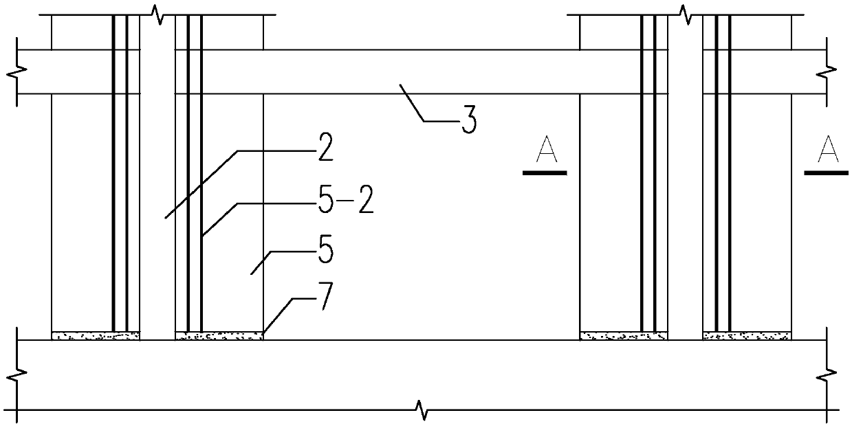
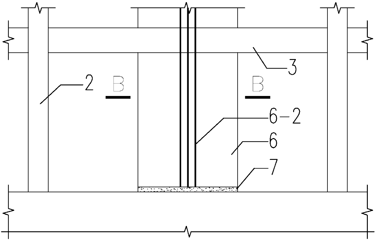
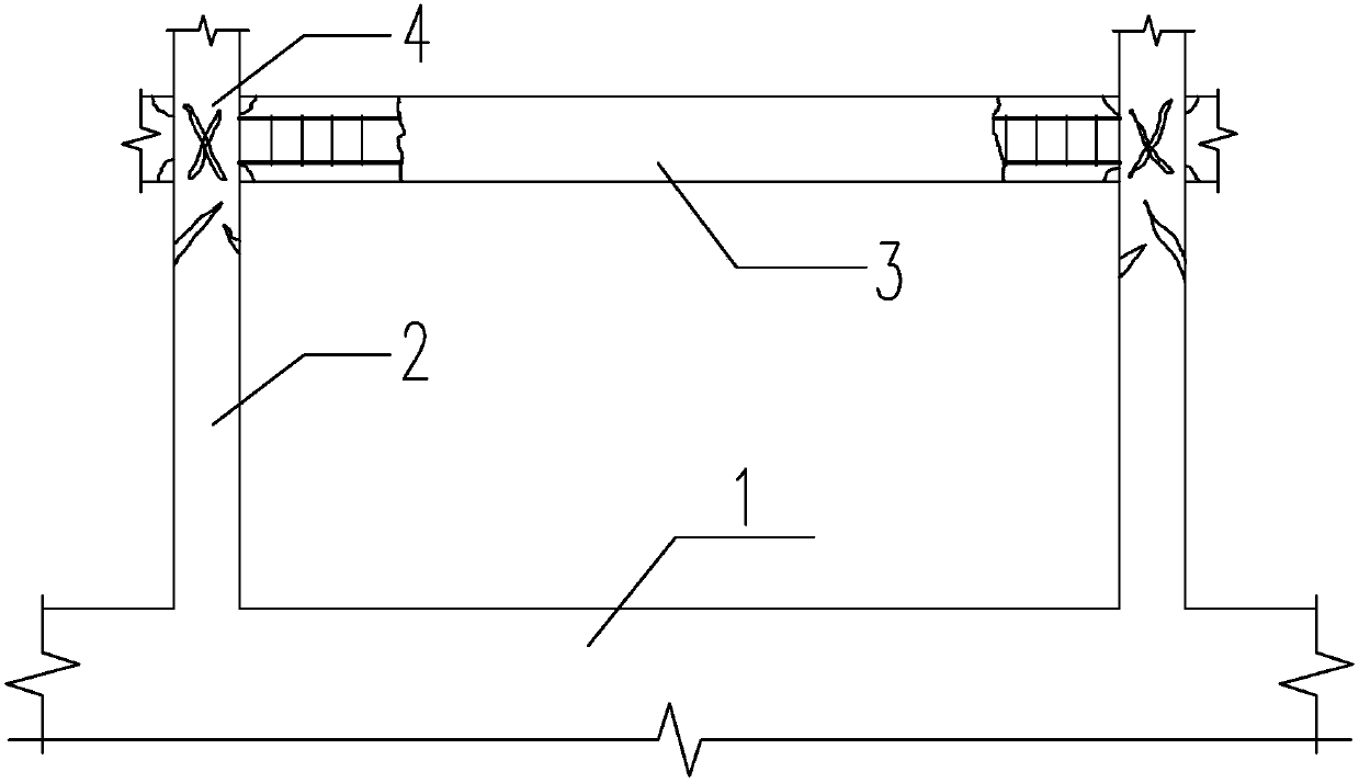
[0046] Specific implementation mode one: combine figure 1 , Figure 3 to Figure 8 and Figure 10 Describe this embodiment, a self-resetting frame-shear wall structure for strengthening the earthquake-damaged frame described in this embodiment includes an earthquake-damaged frame 1, frame columns 2, frame beams 3 and beam-column nodes 4; it also includes multiple Rear shear walls 5 on the column side and fiber cement slurry layer 7, multiple rear shear walls 5 on the column side are arranged symmetrically or on three sides or four sides and installed on the frame column 2, and the rear shear walls 5 on the column side A certain height is reserved at the bottom, and the fiber cement slurry layer 7 is formed by pressure filling within the reserved height range. The reserved height is 25mm-35mm, and the post shear wall 5 is placed on the side of the column on multiple frame column sides within the structural plane range. Arranged as needed, spanning multiple layers in the vertic...

specific Embodiment approach 2

[0049] Specific implementation mode two: combination figure 1 , Figure 7 , Figure 8 and Figure 10 Describe this embodiment, each column-side rear shear wall 5 in this embodiment includes multiple column-side tunnels 5-1, multiple column-side prestressed tendons 5-2, and multiple column-side lower anchors 5-3 , multiple anchors 5-4 on the column side, 5-5 multiple pin key reinforcement bars on the column side, 5-6 vertically distributed reinforcement bars on the column side, 5-7 horizontally distributed reinforcement bars on the column side, and 5 multiple energy-dissipating reinforcement bars on the column side -11; the column side channel 5-1 is vertically arranged parallel to the height direction of the frame column 2, the column side prestressed tendons 5-2 are pierced in the column side channel 5-1, and the lower end of the column side prestressed tendons 5-2 passes through The lower anchor 5-3 on the column side is anchored below the fiber cement slurry layer 7 at t...

specific Embodiment approach 3

[0050] Specific implementation mode three: combination figure 1 , Figure 7 , Figure 8 and Figure 10 To illustrate this embodiment, each column-side rear shear wall 5 of this embodiment also includes column-side tie bars 5-8, column-side edge-constrained longitudinal reinforcements 5-9 and column-side edge-constrained area stirrups 5- 10. The tie bars 5-8 on the column side are arranged at an interval of no more than 600mm in the horizontal direction and the vertical direction, and the double-row reinforcement mesh formed by the vertically distributed steel bars 5-6 on the column side and the horizontally distributed steel bars 5-7 on the column side The bottom of vertically distributed steel bars 5-6 on the column side and the longitudinal bars 5-9 in the restricted area on the edge of the column do not extend into the foundation, and the vertically distributed steel bars 5-6 on the column side and the top of longitudinal bars 5-9 in the restricted area on the edge of the...


PUM


Abstract

The invention provides a self-resetting frame-shear wall structure for reinforcing an earthquake-damaged frame and a construction method and relates to a self-resetting frame-shear wall structure anda construction method. According to the self-resetting frame-shear wall structure for reinforcing the earthquake-damaged frame and the construction method, the problem that at current, after a shear wall is additionally arranged to reinforce an earthquake-damaged concrete frame, large interlayer lateral migration, permanent residual deformation caused by an earthquake and structure damage caused by the earthquake still possibly occur is solved. The self-resetting frame-shear wall structure comprises the earthquake-damaged frame, a column side rear-arranged shear wall or an inter-column rear-arranged shear wall and a fiber cement paste layer, an earthquake-damaged area of the earthquake-damaged concrete frame is restored, then a certain height is reserved for the fiber cement paste layer firstly when the rear-arranged shear wall is constructed, and then arrangement of wall body interior high-strength prestress bars and steel bars and pouring of wall body concrete are conducted. After the grade of the wall body concrete reaches the designed strength grade, tensioning and anchoring are conducted, and fiber cement paste is poured into the reserved height range of the wall bottom in a pressed mode. The self-resetting frame-shear wall structure and the construction method are used for reinforcing the earthquake-damaged frame.

Description

technical field [0001] The invention relates to a self-resetting frame-shear wall structure and a construction method, in particular to a self-resetting frame-shear wall structure and a construction method for strengthening an earthquake-damaged frame, and belongs to the technical field of civil engineering. Background technique [0002] Common concrete frames that are widely used in large quantities have different degrees of earthquake damage after strong earthquakes, and corresponding reinforcement technical measures need to be taken according to the degree of damage. Among them, adding shear walls is a more commonly used reinforcement measure, which can increase the overall rigidity of the structure. Change the stiffness ratio of the components to improve the seismic capacity of the structure. However, the reinforcement method of adding shear walls is still to ensure that the structure does not collapse under rare earthquakes as the safety goal. In the end, there may sti...

Claims


Application Information

Patent Timeline
IPC IPC(8): E04B2/64E04B1/98E04H9/02E04G21/00
CPCE04B2/64E04G21/00E04H9/02
Inventor 周威刘洋赵星谢新莹周益国耿相日丛昕彧
Owner HARBIN INST OF TECH
Why Eureka
Try Eureka