Sparse antenna of forward-looking array SAR system
A sparse antenna and array technology, used in radio wave measurement systems, radio wave reflection/re-radiation, utilization of re-radiation, etc. Achieve the effect of improving the signal-to-noise ratio, increasing the transmit gain, and reducing the number of array elements
- Summary
- Abstract
- Description
- Claims
- Application Information
AI Technical Summary
Problems solved by technology
Method used
Image

Examples
Embodiment Construction
[0024] In order to make the technical solutions and advantages of the present invention clearer, the present invention will be further described below in conjunction with specific embodiments and drawings in the forward-looking array SAR system.
[0025] The invention is mainly applied to the radar imaging of the real-aperture array antenna, and is currently mainly applicable to the short-distance imaging platform of the high-frequency band array radar.
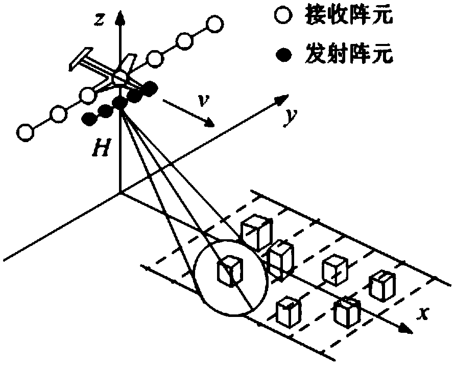
[0026] figure 1 A schematic diagram of the forward-looking array SAR system for earth observation is given. The carrier plane flies horizontally and uniformly along the direction of the observation strip at H meters above the observation strip, and the speed is v. The radar emission beam points to the front and bottom of the platform (using beam scanning to achieve effective coverage of the observation strip, figure 1 Examples of observations for the two-beam case are given). Assuming that the receiving and transmitting an...
PUM
 Abstract
Description
Claims
Application Information
PatSnap Eureka turns technology decisions into work you can execute. Powered by our Innovation Knowledge Graph, it runs expert workflows across engineering, life sciences, materials and intellectual property. Get your review-ready output in minutes.


