Supercharge Your Innovation With Domain-Expert AI Agents!

Multi-process combination machine tool for crankshaft machining

A combined machine tool and crankshaft processing technology, used in metal processing machinery parts, metal processing, metal processing equipment, etc., can solve the problems of easy scratching, low precision, easy bumping of the crankshaft, etc., and improve the quality of hot pressing assembly. , the processing rhythm is compact, the effect of shortening the work rhythm

Pending Publication Date: 2018-04-24
XIANGYANG FUDA DONGKANG CRANKSHAFT
View PDF15 Cites 4 Cited by
  • Summary
  • Abstract
  • Description
  • Claims
  • Application Information

AI Technical Summary

Problems solved by technology

[0007] 1. Multiple processes are required to complete, the cycle is long and the efficiency is low
[0008] 2. The equipment is simple, the production equipment is backward, and the processing technology is simple and rough
The pin hole is drilled using an ordinary desktop drilling machine, which has low precision, simple structure, and large spindle rotation and swing. It is necessary to make a special guide sleeve to ensure the machining accuracy.
[0009] 3. Manual operation and multiple hoisting of the crankshaft, the crankshaft is easy to be bumped and damaged, the labor intensity is high, time-consuming and labor-intensive, the production method is backward, and it cannot adapt to large-scale automatic production
[0010] 4. A large number of operators are required, resulting in a waste of human resources and increasing labor costs
[0011] 5. The drilling machine rotates at high speed, and the operator needs to replace the tool and the drill set many times, which is easy to scratch the hand; and the iron filings are easy to splash and may hurt the eyes; the copper hammer hits the pin and the hand is easy to be injured; the gear installation is easy to burn the finger
Occupational accidents occur frequently, and there are considerable safety hazards
[0012] 6. Multiple replacement of cutting tools and drilling sets, low efficiency
[0013] 7. Difficult to guarantee quality
[0014] 8. When drilling, the operator manually feeds the tool. When the feeding force is uneven, the tool is prone to breakage, resulting in the consumption of tool cost

Method used


Image

  • Multi-process combination machine tool for crankshaft machining
  • Multi-process combination machine tool for crankshaft machining
  • Multi-process combination machine tool for crankshaft machining

Examples


Embodiment Construction

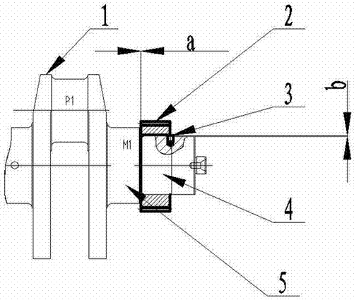
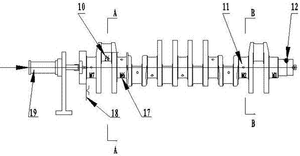
[0040] Such as figure 1 , figure 2 , image 3 , Figure 4 , Figure 5 , Figure 6 , Figure 7 As shown, the pin 3 is press-fitted into the pin hole 12 on the gear journal 4 of the crankshaft 1 with an interference fit. , The inner hole keyway on the gear 2 is aligned with the pin 3 and installed on the gear journal 4 by hot pressing, and the gap between it and the end surface of the M1 main journal 5 is a.

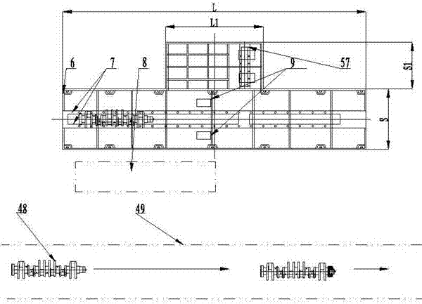
[0041]In order to realize the above-mentioned assembly, when designing the combined machine tool bed, the present invention concentrates and combines all processing components around the bed 36 . The fuselage is designed as a L×S rectangular structure. All processing parts can be placed in the L length direction, and the S width direction can ensure all positioning and clamping tooling positions of the crankshaft 48 to be processed and reserve chip removal holes 9 . Since the Z540 drilling machining center 47 and the pressing pin table 25 need to be placed on the b...


PUM


Abstract

Disclosed is a multi-process combination machine tool for crankshaft machining, and the multi-process combination machine tool is used for quantity production after finish machining of a crankshaft. The combination machine tool is provided with rectilinear guideways in front and back, left and right directions. A drilling hole machining center and a tool changer are fixed on a convex platform position of the combination machine tool. A pressure pin platform is located on the right side of the drilling hole machining center and on the rectilinear guideway in front and back direction. A V-shapedblock, an axial compression device, a pushing and clamping device, and a longitudinal compression device are all fixed on a movable worktable. A gear heating table, a mechanical arm, and a gear frameare all placed on the right side of the pressure pin platform. A truss is fixed on the right side ground surface of an operation station on one side of the combination machine tool, and the upper endof the mechanical arm is arranged on the truss in a sleeving mode. A cooling water tank is located on the right side of a gear heating platform. A gear press fitting device is located on a rectilinear guideway in left and right direction and at the right end of the combination machine tool body and. According to the multi-process combination machine tool for crankshaft machining, multiple-operation machining of crankshaft drilling, expanding, reaming, automatic pin, riveting, gear heating, and hot pressing assembly can be completed continuously; the degree of automation is high; the machiningrhythm is compact; labor intensity is low; and the heat pressure assembly quality of the pressure pin and a gear can be greatly improved.

Description

technical field [0001] The invention relates to the technical field of auto parts manufacturing, in particular to a multi-process combined machine tool for specialized batch production of crankshafts. Background technique [0002] According to the crankshaft processing process, after the crankshaft is finished, there are several processing procedures as follows: [0003] 1. Machining the pin hole on the crankshaft gear journal: hoist the crankshaft on the drilling fixture and clamp and position it, and process the pin hole on the gear journal through another set of drilling jig set tooling. The processing sequence is: the center drill is for the precise positioning of the drill hole; the twist drill drills the bottom hole of the pin hole; the reamer reams the pin hole, and the countersink drill chamfers the pin hole. Above every time a crankshaft is processed, it is necessary to manually change the tool four times, and because the diameters of the center drill, the twist dr...

Claims


Application Information

Patent Timeline
Patent Type & Authority Applications(China)
IPC IPC(8): B23Q37/00B23Q7/04B23Q11/00
CPCB23Q7/04B23Q11/0042B23Q37/00Y02P70/10
Inventor 李小新王长顺康笃玲李绵丰
Owner XIANGYANG FUDA DONGKANG CRANKSHAFT
Features
  • R&D
  • Intellectual Property
  • Life Sciences
  • Materials
  • Tech Scout
  • Unparalleled Data Quality
  • Higher Quality Content
  • 60% Fewer Hallucinations
Learn More