

Double-impeller mechanical stirring self-suction flotation machine and flotation method
A mechanical stirring and self-priming technology, which is applied in flotation, solid separation, etc., can solve the problems of reduced negative pressure intensity, little chance of breaking through the adhesion of hydration film, and inconvenient maintenance and maintenance, etc. The probability of mineralization, the effect of improving the mineralization effect of air bubbles, and the effect of excellent aerated foaming performance
Active Publication Date: 2018-05-01
WUHAN INSTITUTE OF TECHNOLOGY
View PDF7 Cites 19 Cited by
- Summary
- Abstract
- Description
- Claims
- Application Information
AI Technical Summary
Problems solved by technology
The disadvantages of this matching mode are: (1) The air filling volume of the flotation machine is limited by the rotor speed. To increase the air filling volume, the rotor speed needs to be increased to form a greater negative pressure intensity, but mineral separation requires the flotation machine The rotation speed should be low to create a better static flow separation environment, avoid mechanical inclusions to reduce the concentrate grade and recovery rate, and there is a contradiction between the aeration volume and the rotation speed, which can only be relatively optimized; (2) Suction negative pressure The air and ore pulp in the area are transported to the flotation cell through the rotor, so the air bubbles and the ore pulp formed basically move in the same direction, which is not conducive to the collision mineralization of air bubbles and hydrophobic mineral particles, and the fine particles mixed with air bubbles are hydrophilic Mineral particles also have no scouring effect, and the sorting accuracy is often not high enough; (3) In order to ensure the amount of inflation, the rotor speed is relatively fast, the energy consumption is large, and the rotor and stator are easy to wear, resulting in a gradual decrease in the negative pressure intensity generated. The amount of aeration keeps decreasing, and the liquid level of the slurry is not stable; (4) The structure of the system is relatively complicated, and the maintenance and maintenance are not convenient enough
[0004] Flotation column; although the structure is simple, the floor area is small, the investment cost is low, the gas filling volume is easy to adjust and control, the reverse movement of the pulp and the air bubbles has a certain scouring effect on the air bubbles, and it is beneficial to improve the separation accuracy, but in practical applications the same There are some problems: (1) Most of the existing flotation columns use jet devices to inflate and foam. Under certain flotation medium conditions, the pipelines of the jet devices are easy to foul and block and are inconvenient to replace; (2) Although the hydrophobic mineral particles The probability of collision with the reverse movement of the bubbles is relatively high, but only relying on the gravity of the mineral particles and the buoyancy of the bubbles, the probability of them breaking through the hydration film and sticking to each other is not high, and the flotation time required is longer; (3) In order to ensure the flotation The height of the flotation column is generally relatively high, which inevitably leads to uneven distribution of gas and liquid in the flotation column, and the flotation conditions are not easy to control; (4) Additional slurry pumps are required for medium ore circulation and slurry transportation. High energy consumption; (5) In case of a sudden power failure, the slurry in the column needs to be emptied, and a storage pool needs to be set up
Because of this, the flotation column is difficult to be popularized and applied on a large scale in production so far
Method used
View moreImage
Smart ImageViewing Examples

Examples
Embodiment 1
[0026] Embodiment 1: The ore sample used in the test is Hubei Yuan'an phosphate rock, and the main chemical composition is (w / %): P 2 o 5 22.16, MgO3.15, SiO 2 25.41, Al 2 o 3 7.39, CaO 29.85, Fe 2 o 3 1.69, K 2 O 2.31, TiO 2 0.63. The positive flotation roughing comparison test was carried out under the same reagent conditions, that is, the flotation foam product was phosphorus concentrate, and the tank bottom product was impurity tailings. The best flotation results obtained are shown in Table 1.
Login to View More PUM
 Abstract
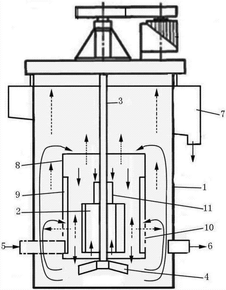
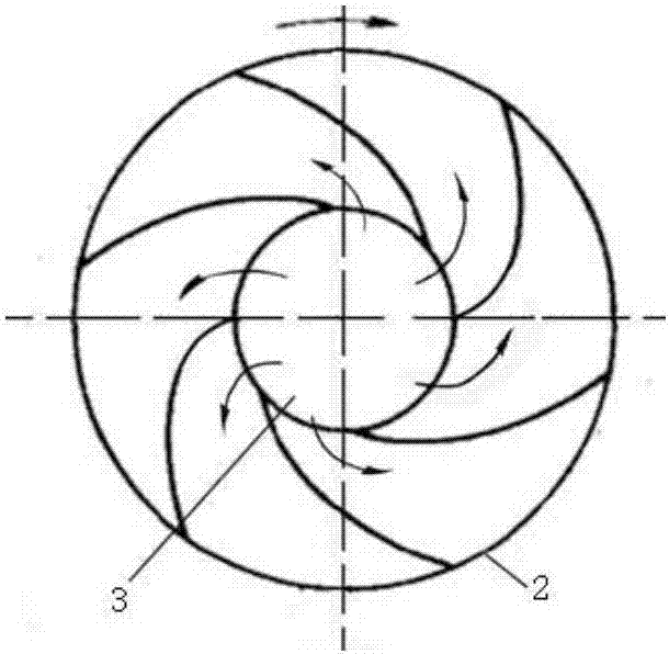
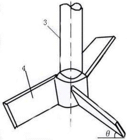
The invention provides a double-impeller mechanical stirring self-suction flotation machine and a flotation method. The double-impeller mechanical stirring self-suction flotation machine comprises a column type flotation cell, a rotary shaft, an upper impeller and a lower impeller, wherein the rotary shaft is vertically inserted into the center of the inner part of the column type flotation cell;the upper impeller is fixed to the middle lower part of the rotary shaft; the lower impeller is fixed to the lower part of the rotary shaft; a guide cylinder sleeves outside the upper impeller; the lower impeller is located on the outer side of the bottom part of the guide cylinder; guide plates are arranged on an inner wall of the guide cylinder along a circumferential direction at intervals; circulation holes are uniformly distributed on the lower part of the guide cylinder along the circumferential direction; an ore feeding pipe and an ore discharging pipeline are symmetrically arranged ontwo sides of the lower part of the flotation cell; the ore feeding pipe is connected with the guide cylinder; and a foam tank is arranged on the upper part outside the flotation cell. According to thedouble-impeller mechanical stirring self-suction flotation machine and the flotation method provided by the invention, a flotation bubble mineralization effect can be improved, a flotation three-phase flow field separation environment is optimized, the reverse flow of an ore pulp and bubbles is realized, and the efficiency and the separation precision of a flotation process are improved.
Description
technical field [0001] The invention belongs to the technical field of flotation equipment, and in particular relates to a mechanically agitated flotation machine and a flotation method. Background technique [0002] Flotation is a very effective mineral separation method. Although there are many types of flotation equipment, they are mainly divided into two categories: flotation machines and flotation columns. Among them, the most widely used is the mechanical agitation flotation machine. The core of the mechanical agitation flotation machine is the rotor (impeller) and stator system of the agitation device, which can be divided into two types: self-suction type and compressed air type according to different inflation methods. Although the compressed air type is easier to adjust and control the inflation volume, it requires additional air compression equipment, so self-priming equipment is often used in production. The mechanical agitation self-priming flotation machine ...
Claims
Login to View More Application Information
Patent Timeline
 Patent Type & AuthorityApplications(China)
IPC IPC(8): B03D1/16
Inventor张泽强唐柳华
OwnerWUHAN INSTITUTE OF TECHNOLOGY