Burst-pulse-mode ultra-fast laser and working method thereof

A burst pulse and laser technology, used in lasers, laser parts, phonon exciters, etc., can solve problems such as changes in laser reliability and stability, loss of laser output power, and changes in laser output characteristics, and achieve high gain. , large bandwidth, and the effect of solving heat accumulation

Pending Publication Date: 2018-05-11
褚宏伟
View PDF9 Cites 11 Cited by
  • Summary
  • Abstract
  • Description
  • Claims
  • Application Information

AI Technical Summary

Problems solved by technology

Moreover, in order to maintain high power output for a long time, not only the heat accumulation effect occurs in the laser medium, but also the heat is accumulated on the receptor due to the action of continuous pulse trains, which not only changes the output characteristics of the laser itself , will also change the characteristics of the receptor substance itself, which is difficult to control and is not conducive to practical application in industry and commerce
[0003] From the above discussion, it can be concluded that at present, there are two main problems in ultrafast lasers that restrict its commercial and industrial development: first, the gain saturation of the gain medium makes the output power of the laser lose the space for further improvement; second 2. During the operation, the thermal efficiency of the laser amplification medium and the heat accumulation caused by the continuous pulse train change the reliability and stability of the laser

Method used


Image

  • Burst-pulse-mode ultra-fast laser and working method thereof
  • Burst-pulse-mode ultra-fast laser and working method thereof
  • Burst-pulse-mode ultra-fast laser and working method thereof

Examples


Embodiment 1

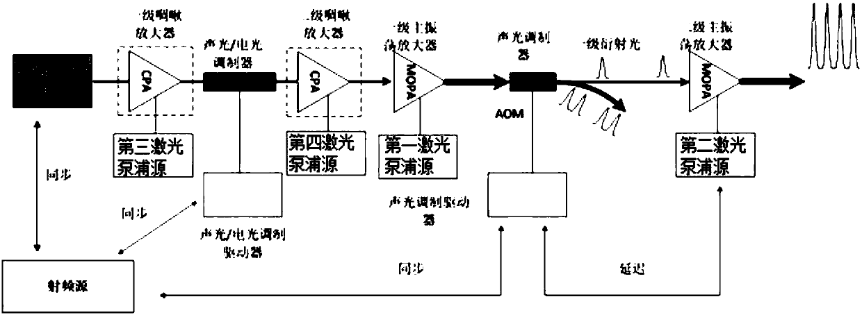
[0076] A burst-mode ultrafast laser, such as figure 1As shown, including radio frequency source, laser oscillator, fiber-coupled acousto-optic / electro-optic modulator, acousto-optic / electro-optic modulation driver, first-stage main oscillator amplifier, acousto-optic modulator, acousto-optic modulation driver, laser oscillator, fiber-coupled acoustic The optical / electro-optic modulator, the first-stage main oscillator amplifier, and the acousto-optic modulator are placed along the optical path in sequence; the acousto-optic / electro-optic modulation driver is connected to the fiber-coupled acousto-optic / electro-optic modulator, and the acousto-optic modulation driver is connected to the acousto-optic modulator;

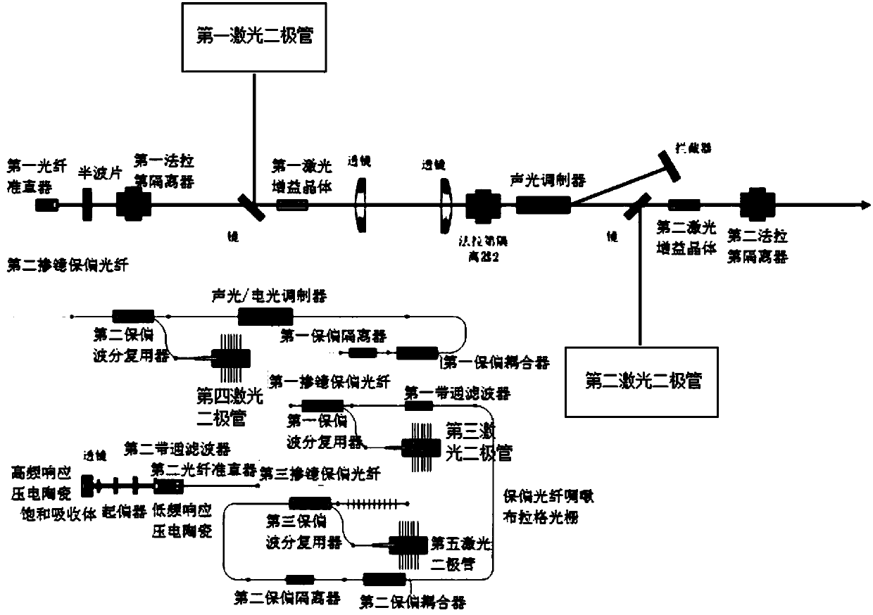
[0077] The first-stage main oscillator amplifier includes a half-wave plate, a first Faraday isolator, a first laser diode, and a first laser gain crystal placed behind the fiber-coupled acousto-optic / electro-optic modulator and placed sequentially along the optical pat...

Embodiment 2

[0094] According to a kind of burst pulse mode ultrafast laser described in embodiment 1, its difference is that,

[0095] The burst pulse mode ultrafast laser also includes a secondary main oscillator amplifier, which includes a second Faraday isolator, a second laser diode, and a second laser gain amplifier placed behind the acousto-optic modulator and placed sequentially along the optical path. crystal; the second laser gain crystal is Nd:YVO4 crystal.

[0096] In view of the low optical power of the burst pulse mode, generally only 1% of the output power of the first-stage main oscillator amplifier, in order to further increase the output power and output energy, a second-stage main oscillator amplifier can be established for further amplification, and the output power of the second-stage main oscillator amplifier The structure is consistent with that of the first-stage main oscillator amplifier.

[0097] After the burst pulse mode is generated by the acousto-optic / electr...

Embodiment 3

[0099] A kind of burst mode ultrafast laser according to embodiment 1 or 2, such as figure 2 As shown, the difference is that

[0100] The burst mode ultrafast laser also includes a first-stage chirped amplifier and a second-stage chirped amplifier. The first-stage chirped amplifier is set between the laser oscillator and the fiber-coupled acousto-optic / electro-optic modulator; the second-stage chirped amplifier is set at Between the fiber-coupled acousto-optic / electro-optic modulator and the first-stage main oscillator amplifier.

[0101] When the output power of the burst pulse mode ultrafast laser is far less than 10mW, it is amplified by a first-stage chirped amplifier to improve the output power and signal-to-noise ratio of the fiber-coupled acousto-optic / electro-optic modulator; when n>10, it is amplified by a second-stage The chirped amplifier amplifies the output power of the ultrafast laser in burst mode.

[0102] Considering the spontaneous emission amplification ...


PUM


Abstract

The invention relates to a burst-pulse-mode ultra-fast laser and a working method thereof. The ultra-fast laser comprises a radio frequency source, a laser oscillator, an optical fiber coupling acousto-optic / electro-optic modulator, an acousto-optic / electro-optic modulation driver, a first-stage main oscillation amplifier, an acousto-optic modulator and an acousto-optic modulation driver. The laser oscillator, the optical fiber coupling acousto-optic / electro-optic modulator, the first-stage main oscillation amplifier and the acousto-optic modulator are arranged along an optical path in sequence. The acousto-optic / electro-optic modulation driver is connected with the optical fiber coupling acousto-optic / electro-optic modulator; and the acousto-optic modulation driver is connected with the acousto-optic modulator. A light beam is output from the laser oscillator having stable pulse repetition frequency frep; the pulse repetition frequency is reduced to frep / n through the optical fiber coupling acousto-optic / electro-optic modulator; then, the light beam is amplified by the first-stage main oscillation amplifier; and finally, the acousto-optic modulator produces a burst pulse mode.

Description

technical field [0001] The invention relates to a burst pulse mode ultrafast laser and a working method thereof, belonging to the technical field of ultrafast lasers. Background technique [0002] Ultrafast lasers are key technologies in many industrial processing, free electron lasers, electron accelerators and other fields. Mode-locked lasers can generate ultrafast pulses, but their output energy is generally on the order of nanojoules, which is difficult to apply directly. To realize the practical application of ultrafast lasers, it is mainly necessary to solve the problem of low output power. The commonly used amplification technique is the master oscillator power amplification system (MOPA). In most MOPA designs, there is a contradiction between the gain saturation caused by achieving high efficiency and the need for a sufficiently large gain to achieve high amplification. That is to say, in order to increase the output power, MOPA requires a high gain, and the high p...

Claims


Application Information

Patent Timeline
Patent Type & Authority Applications(China)
IPC IPC(8): H01S3/11H01S3/067H01S3/094
CPCH01S3/06712H01S3/094076H01S3/1106
Inventor 褚宏伟
Owner 褚宏伟
Why Eureka
Try Eureka