
Steam reheating system for waste incineration boiler

A waste incineration and heating system technology, applied in the field of waste incinerator heating equipment, can solve the problems of weak reheat steam cooling capacity, high temperature corrosion of reheater, and unguaranteed service life, so as to reduce investment cost and floor area, Improve heat transfer efficiency and reduce high temperature corrosion

Inactive Publication Date: 2018-05-15
SHENZHEN ENERGY ENVIRONMENT ENG
View PDF10 Cites 4 Cited by
  • Summary
  • Abstract
  • Description
  • Claims
  • Application Information

AI Technical Summary

Problems solved by technology

However, it has the following potential problems: 1. Due to the weak cooling capacity of the reheat steam, placing the two-stage reheater before the high-temperature superheater will cause the reheater to suffer severe high-temperature corrosion in a relatively high flue gas temperature environment , even if spraying or anti-corrosion materials are used, the cost is relatively high, and the service life cannot be guaranteed; 2. The two-stage reheater is arranged in front of the high-temperature superheater, and the reheated steam is heated to 450°C, which will cause flue gas and overheating The temperature compression between the steam of the device is small, which reduces the heat transfer efficiency
In order to ensure the main steam temperature, more superheater area needs to be arranged in the design, which will greatly increase the investment cost of the waste incineration boiler

Method used


Image

  • Steam reheating system for waste incineration boiler

Examples


Embodiment Construction

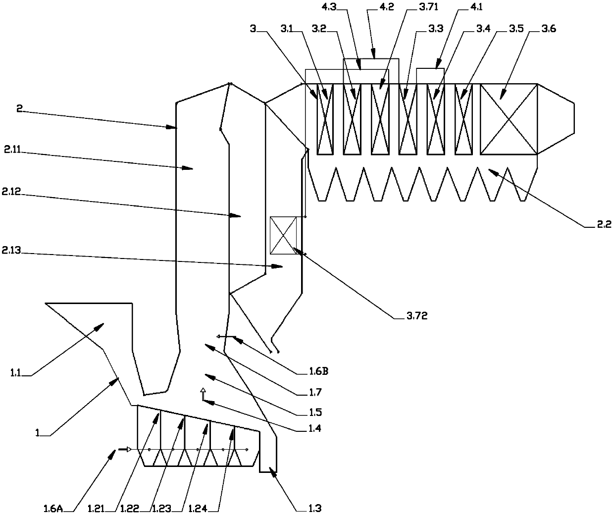
[0027] figure 1 It is a schematic diagram of the structural arrangement of an embodiment proposed by the present invention. As shown in the figure, a waste incineration boiler superheater system mainly includes a grate 1.2, a furnace 1.5, a flue 2 and a heat receiver 3. The grate 1.2 includes a drying section 1.21, a pyrolysis section 1.22, a combustion section 1.23, and a burnout section 1.24, the flue 2 includes the first vertical flue 2.11, the second vertical flue 2.12, the third vertical flue 2.13 and the horizontal flue 2.2, and the heat receiver 3 includes the primary evaporator 3.1, the third superheater 3.2, the second Stage superheater 3.3, stage one superheater 3.4, stage two evaporator 3.5, and economizer group 3.6, arrange stage one evaporator 3.1, stage three superheater 3.2, stage two Superheater 3.3, primary superheater 3.4, secondary evaporator 3.5 and economizer group 3.6.

[0028] figure 1 It shows that the furnace body 1 mainly includes the grate 1.2, th...


PUM


Abstract

The invention provides a reheater system for a waste incineration boiler. The reheater system aims at solving the problems. Due to the fact that a high-temperature reheater and a low-temperature reheater are additionally arranged and the high-temperature reheater and the low-temperature reheater are separately arranged, to improve the smoke environment where the high-temperature reheater is located and reduce high-temperature corrosion, the high-temperature reheater is arranged behind a horizontal flue third-stage superheater and in front of a second-stage superheater. To reduce the total length of the boiler, the low-temperature reheater is arranged in a third vertical flue, so that it can be guaranteed that the main steam temperature of the waste heat boiler is increased to 450 DEG C to480 DEG C, the reheating steam temperature reaches 400-450 DEG C, the safety and reliability of the reheaters can be improved, the heat exchange efficiency of the boiler is improved, no excess superheater area needs to be increased, the investment cost and the occupied area of the boiler are lowered, and the problems existing in the prior art can be solved effectively.

Description

technical field [0001] The invention relates to heating equipment for garbage incinerators, in particular to a steam reheating system for garbage incinerators. Background technique [0002] In view of the fact that compared with sanitary landfill, composting and other waste treatment technologies, incineration treatment technology has obvious effects of volume reduction and weight reduction, is completely harmless, and occupies a small area. In addition, waste heat can also be used for heating or power generation. With the advantages of less pollution and controllability, it has gradually become the mainstream technology for municipal solid waste treatment in my country. [0003] However, since garbage contains a large amount of Cl elements, it will produce HCl, Cl2 and other corrosive gases and other corrosive chlorides after combustion, which will corrode the high-temperature heating surface of the boiler, and this corrosion phenomenon will increase with the increase of the...

Claims


Application Information

Patent Timeline
Patent Type & Authority Applications(China)
IPC IPC(8): F22B31/08F22G5/12F22G3/00F23G5/027F23G5/44
CPCF22B31/08F22G3/00F22G5/123F23G5/027F23G5/44
Inventor 吴燕琦沈竑刘国辉
Owner SHENZHEN ENERGY ENVIRONMENT ENG
Learn More