System and method for monitoring critical state of power electronic device in strong electromagnetic environment

A technology of power electronics and key states, applied in the direction of measuring electricity, measuring devices, measuring electrical variables, etc., can solve problems such as internal short circuit, operating system instability, deviation from flight trajectory, etc., and achieve high anti-interference ability and reliability, parameters The effect of flexible setting and high communication accuracy

Active Publication Date: 2018-05-15
武汉天富海科技发展有限公司
View PDF7 Cites 3 Cited by
  • Summary
  • Abstract
  • Description
  • Claims
  • Application Information

AI Technical Summary

Problems solved by technology

The spike voltage caused by electromagnetic interference can increase the impurity concentration at a certain point in the emitter junction and collector junction, resulting in transistor breakdown or internal short circuit
Transistors operating under strong radio-frequency electromagnetic fields can absorb enough energy to cause damage to the junction temperature beyond the allowable temperature rise
[0014] (2) The strong electromagnetic radiation field can cause the sensitive weapon detonating device installed in the power electronic equipment system to run out of control and start prematurely; for guided missiles, it will cause deviation from the flight trajectory and increase the distance error; for aircraft, it will Cause operating system instability, heading inaccuracy, altitude display error, radar antenna tracking position deviation, etc.

Method used


Image

  • System and method for monitoring critical state of power electronic device in strong electromagnetic environment
  • System and method for monitoring critical state of power electronic device in strong electromagnetic environment
  • System and method for monitoring critical state of power electronic device in strong electromagnetic environment

Examples


Embodiment Construction

[0061] In order to make the object, technical solution and advantages of the present invention clearer, the present invention will be further described in detail below in conjunction with the accompanying drawings and embodiments. It should be understood that the specific embodiments described here are only used to explain the present invention, not to limit the present invention.

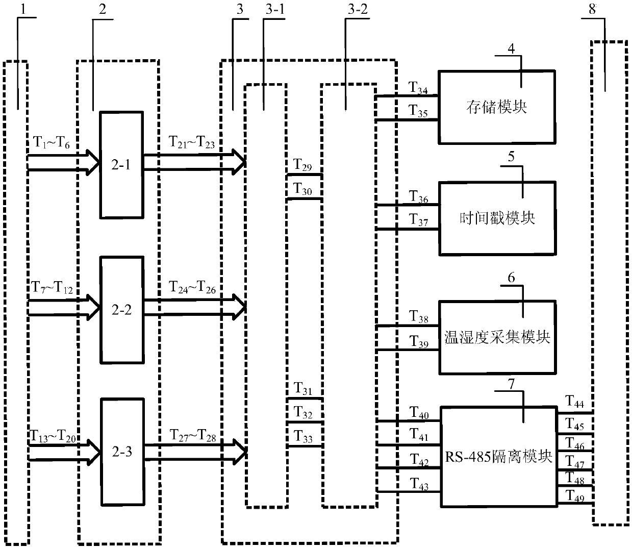
[0062] The purpose of the present invention is to provide a system for monitoring the key state of power electronic equipment in a strong electromagnetic environment, which can not only obtain its own health status in real time, but also work normally in a strong electromagnetic field environment, and handle strong electricity and weak electricity strictly, correctly and reasonably to improve Conversion efficiency and reliability of power electronic devices.

[0063] In order to achieve the above object, the technical solution adopted by the present invention is: the system for monitoring the criti...


PUM


Abstract

The invention provides a system and method for monitoring the critical state of a power electronic device in a strong electromagnetic environment. The system comprises a first user interface module, an eight-channel signal acquisition module, a main control module, a storage module, a time stamp module, a temperature and humidity acquisition module, a dual RS-485 isolation module and a second userinterface module. The first user interface module is used to acquire eight analog signals reflecting the critical state of the power electronic device. The main control module comprises a multiplex switch unit and an ARM main control unit. The ARM main control unit communicates with the storage module, the time stamp module and the temperature and humidity acquisition module at the same time. TheARM main control unit acquires a real-time time stamp through the time stamp module, and stores data with the time stamp in the storage module. The temperature and humidity acquisition module monitors the temperature and humidity of the ARM main control unit. External data transmission is carried out through the dual RS-485 isolation module and the second user interface module.

Description

technical field [0001] The invention belongs to the intersection field of embedded technology and power electronics technology, and more specifically relates to a system and method for monitoring key states of power electronics equipment in a strong electromagnetic environment. Background technique [0002] At present, power electronic equipment is developing towards high voltage, high current, integration and intelligence, especially with SCR (phase-controlled thyristor), IGBT (insulated gate bipolar transistor), IGCT (integrated gate commutated thyristor), etc. The engineering application and promotion of large-capacity power electronic devices represented by the company is not only to solve the current labor-intensive and technology-intensive status quo in the field of power electronics technology, but also to maximize the application potential of large-capacity power electronic devices, and successfully solve engineering problems. Technical problems of reliable, safe and...

Claims


Application Information

Patent Timeline
Patent Type & Authority Applications(China)
IPC IPC(8): G01R31/00
CPCG01R31/003
Inventor 屈碧环
Owner 武汉天富海科技发展有限公司
Why Eureka
Try Eureka