PET detector position coding circuit, method and device
A technology of detector position and encoding circuit, which is applied in the direction of measuring devices, instruments, scientific instruments, etc., can solve the problems of high electronic complexity, achieve the effect of maintaining time performance and positioning accuracy, and reducing electronic complexity
- Summary
- Abstract
- Description
- Claims
- Application Information
AI Technical Summary
Problems solved by technology
Method used
Image

Examples
Embodiment 1
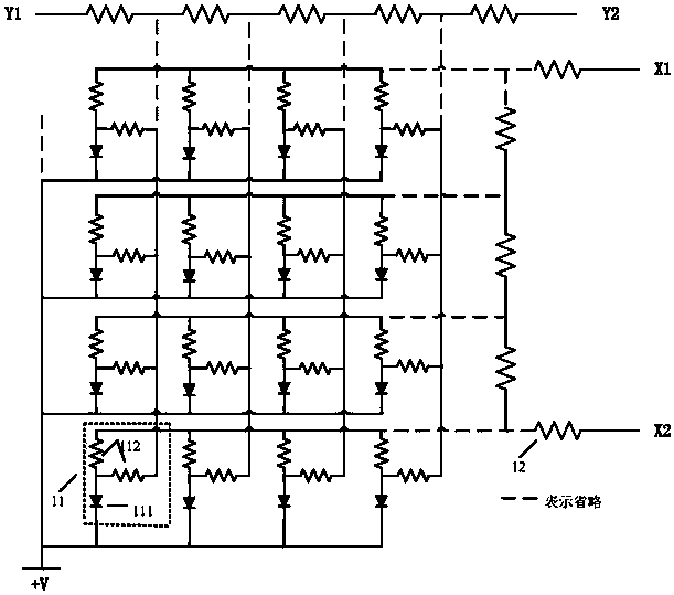
[0025] figure 1 A position encoding circuit of a PET detector with a common-cathode M*N array structure provided by Embodiment 1 of the present invention is shown. For convenience of description, only parts related to the embodiment of the present invention are shown.
[0026] The PET detector position encoding circuit in the embodiment of the present invention includes M*N detection units 11 and a resistor voltage divider circuit, the resistor voltage divider circuit includes M+N+2 resistors 12, and the detection unit 11 includes a photodetector 111 and two shunt resistors 112, one end of the two shunt resistors 112 is connected to one end of the photodetector 111, the other end of a shunt resistor in the two shunt resistors 112 is connected to the corresponding row signal line, and the other end of the two shunt resistors 112 The other end of a shunt resistor is connected to the corresponding column signal line, each row signal line is connected to two resistors 12, each col...
Embodiment 2
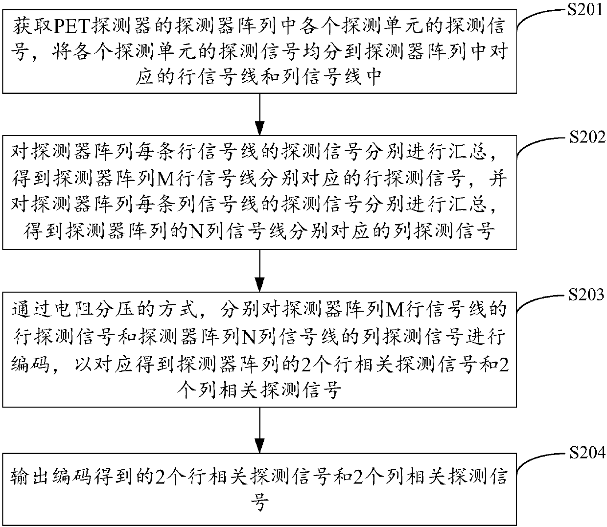
[0029] figure 2 It shows the implementation process of the detector position encoding method of the PET detector provided by Embodiment 2 of the present invention. For the convenience of description, only the parts related to the embodiment of the present invention are shown, and the details are as follows:
[0030] In step S201, the detection signals of each detection unit in the detector array of the PET detector are obtained, and the detection signals of each detection unit are evenly divided into the corresponding row signal lines and column signal lines in the detector array. It is an M*N array, and the detector array includes M*N detection units.
[0031] The embodiment of the present invention is applicable to the PET detector including the detector array described in the first embodiment, so as to facilitate position coding of the detectors in the detector array. In the embodiment of the present invention, the detector array is an M*N array, and the detector array in...
Embodiment 3
[0041] Figure 4 The structure of the detector position encoding device of the PET detector provided by the third embodiment of the present invention is shown. For the convenience of description, only the parts related to the embodiment of the present invention are shown, including:
[0042] The signal distribution unit 41 is used to obtain the detection signals of each detection unit in the detector array of the PET detector, and divide the detection signals of each detection unit into corresponding row signal lines and column signal lines in the detector array. The detector array is an M*N array, and the detector array includes M*N detection units.
[0043] In the embodiment of the present invention, the PET detector includes the position encoding circuit described in Embodiment 1. The detector array of the PET detector is an M*N array, and the detector array includes M*N detection units. The method of applying bias voltage to each detection unit can be a common cathode met...
PUM
 Abstract
Description
Claims
Application Information
 - R&D Engineer
- R&D Manager
- IP Professional
- Industry Leading Data Capabilities
- Powerful AI technology
- Patent DNA Extraction
Browse by: Latest US Patents, China's latest patents, Technical Efficacy Thesaurus, Application Domain, Technology Topic.
© 2024 PatSnap. All rights reserved.Legal|Privacy policy|Modern Slavery Act Transparency Statement|Sitemap