Method for removing silicon in negative hardness wastewater

A hardness and waste water technology, applied in chemical instruments and methods, water/sewage treatment, water/sewage treatment equipment, etc., can solve the problems of difficult removal of effluent silicon compounds, failure to achieve expected results, low lime utilization rate, etc., to increase Silicon removal rate, wide range, and the effect of reducing the amount of sludge discharge

Active Publication Date: 2018-05-22
北京翰祺环境技术股份有限公司
View PDF1 Cites 3 Cited by
  • Summary
  • Abstract
  • Description
  • Claims
  • Application Information

AI Technical Summary

Problems solved by technology

Among them, the method of using lime coagulation precipitation to remove silicon is a low-cost and widely used silicon removal method, but this method has some shortcomings. Due to the characteristics of lime itself, the lime utilization rate is low and the dosage is large. It is difficult to remove silicon compounds in the effluent to a low level, and this method is difficult to achieve for sewage with high effluent requirements
Especially when dealing with silicon in water with negative hardness, the effect of adding pure lime on the removal of silicon is poor, and the expected effect cannot be achieved at all.

Method used


Image

  • Method for removing silicon in negative hardness wastewater

Examples


Embodiment 1

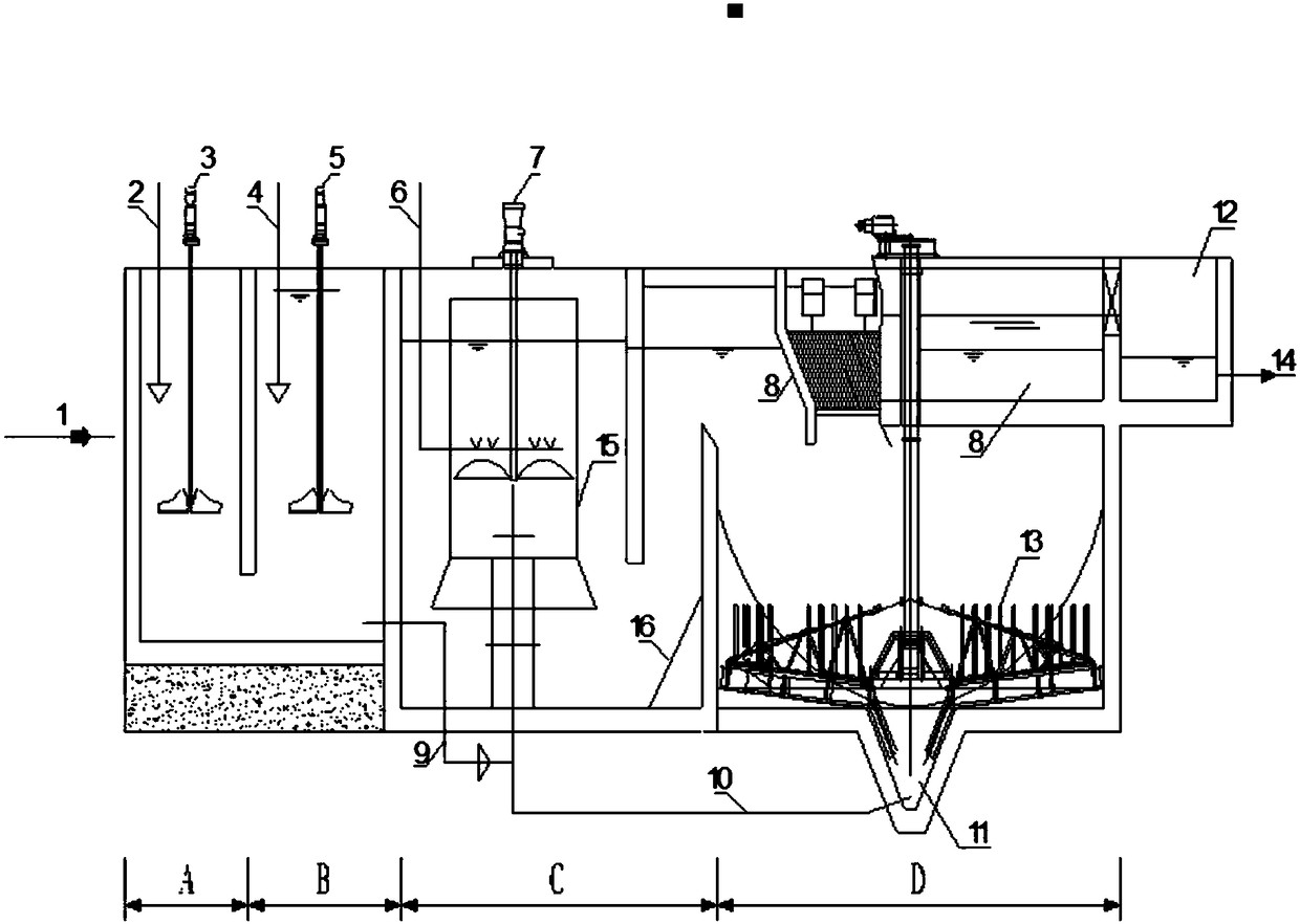
[0020] The water quality of an oilfield waste water contains 1740mg / L of silicon (as SiO 2 After lime and calcium chloride dosing area A, the amount of lime added is 2.1g / L, calcium chloride is 3.1g / L, rapid stirring and reaction in area A for 20min, and PAC is added in coagulation area B 100mg / L, the fast stirring time is 3min in the B area; 1.0mg / L PAM is added in the flocculation area C, and the slow stirring time is 12min in the D area; in the precipitation-concentration area D, the mud and water are separated rapidly, and the clear water is upward The sludge is separated into the sump through the inclined pipe, and the sludge sinks downward. The sludge is concentrated by the thickening sludge scraper and then discharged, and 4% of the sludge is returned to the flocculation zone C; the final effluent quality contains 11.9mg / L of silicon, The silicon removal rate reaches 99.3%.

Embodiment 2

[0022] The water quality of a gasification sewage water contains 98mg / L of silicon (as SiO 2 After lime and calcium chloride dosing area A, add lime at 0.26g / L and calcium chloride at 0.5g / L, stir and react in area A for 18min; add PAC at coagulation area B at 100mg / L, the fast stirring time in B area is 3min; the flocculation area C dosing PAM is 0.5mg / L, and the slow stirring time in D area is 12min; in the precipitation-concentration area D, the mud and water are separated rapidly, and the clear water flows upward , separated into the sump through the inclined tube, the sludge sinks, the sludge is concentrated by the thickening sludge scraper and then discharged, and 6% of the sludge is returned to the flocculation zone C; the final effluent quality contains 12.5mg / L of silicon, except The silicon rate reaches 87.2%.

Embodiment 3

[0024] The water quality of a water plant's reclaimed water contains 200mg / L of silicon (as SiO 2 After lime and calcium chloride dosing area A, add lime at 1.2g / L and calcium chloride at 2.1g / L, stir and react in area A for 20min; add PAC at coagulation area B at 100mg / L L, fast stirring time in B area is 3min; flocculation area C dosing PAM is 1.0mg / L, slow stirring time in D area is 12min; in precipitation-concentration area D, mud and water are separated rapidly, clear water flows upwards, The sludge is separated into the sump through the inclined tube, the sludge sinks, the sludge is concentrated by the thickening sludge scraper and then discharged, and 6% of the sludge is returned to the flocculation zone C; the final effluent quality contains 13.9mg / L of silicon, and the silicon is removed The rate reached 93.1%.


PUM


Abstract

The invention discloses a method for removing silicon in negative hardness wastewater, the silicon in the negative hardness wastewater is effectively removed, and lime, calcium chloride or calcium sulfate, a coagulant and a flocculant are added and have a synergistic interaction in the efficient settling pond process to remove the silicone. The defects of large dosage of the lime and low silicon removal efficiency in the common process of removing the silicon in the negative hardness wastewater by using the lime are improved, and the efficient utilization of the lime is realized. The method has the characteristics of low silicon content of effluent, low drug consumption, wide range of content of removed silicon, high solid content of the sludge, and small occupied area.

Description

technical field [0001] The invention relates to the field of water treatment, in particular to a method for removing silicon from negative hardness wastewater. Background technique [0002] Silicon compounds in industrial water will cause different degrees of harm to the production process. Silicon compounds in industrial boiler feed water, geothermal water and cooling water are prone to form silicon scale, and the formed silicon scale is dense and hard, which is difficult to clean with ordinary methods, seriously affecting the heat transfer efficiency and safe operation of equipment; in the electronic industry water, Silicon dioxide will cause great harm to the production of semiconductors on the surface of monocrystalline silicon, reducing the quality of electronic tubes and solid circuits; in the paper industry, the content of silicon dioxide is too high, which will make the paper brittle; in the rayon industry water If the content of silicic acid is too high, it will af...

Claims


Application Information

Patent Timeline
Patent Type & Authority Applications(China)
IPC IPC(8): C02F1/52C02F1/56
CPCC02F1/5245C02F1/5281C02F1/56C02F2001/007C02F2201/007
Inventor 王晓阳盛雪芹杨权陈立辉谢晓朋郝翰
Owner 北京翰祺环境技术股份有限公司
Why Eureka
Try Eureka