Steel sheet for can and manufacturing method thereof

a technology of steel sheets and cans, applied in the direction of manufacturing tools, furnaces, heat treatment equipment, etc., can solve the problems of deterioration of weldability, increased springback, and hardly guaranteed yield of finished products or materials, and achieve excellent secondary forming properties and reduce canmaking costs

Inactive Publication Date: 2001-04-24
KAWASAKI STEEL CORP
View PDF8 Cites 16 Cited by
  • Summary
  • Abstract
  • Description
  • Claims
  • Application Information

AI Technical Summary

Benefits of technology

Thinning of materials is pursued from the viewpoint of reducing canmaking costs, and the present invention is directed to meeting the demands of canmakers. Accordingly, the thickness is preferably controlled t

Problems solved by technology

When the can height decreases in the secondary forming, the can capacities of finished products or the yields of materials are hardly ensured.
If the material strength (hardness) is low, the can body strength cannot be ensured, whereas if the yield strength (YS) of the material is excessively high, springback increases and weldability is deteriorated due to decreasing the roundness of the cylinder or variations in lap allowance.
According to the process (i) of subjecting a low-C steel to box annealing, however, workability in secondary forming generally tends to be satisfactory, but the r-value can hardly be decreased, so that the decrease in can height cannot be avoided.
According to this process, crystal grains are liable to become coarse and rough surfaces are somewhat liable to occur, inviting defective appearance.
In addition, the steel become soft and the strength is hardly ensured, whereas if the steel is subjected to a generally-employed secondary rolling, it becomes hard, inviting an exce

Method used


Image

  • Steel sheet for can and manufacturing method thereof
  • Steel sheet for can and manufacturing method thereof
  • Steel sheet for can and manufacturing method thereof

Examples


example 1

A series of steels having chemical compositions shown in Table 1 were prepared by steel making in a converter and subjected to continuous casting to give slabs. These slabs were subjected to hot-rolling, cold-rolling, continuous annealing, and secondary cold-rolling under conditions shown in Table 2 to give cold-rolled steel sheets of 0.22 mm in finishing delivery thickness. Subsequently, the steels were subjected to continuous tin plating corresponding to #25 in a tin electroplating line of halogen type to give tinplates.

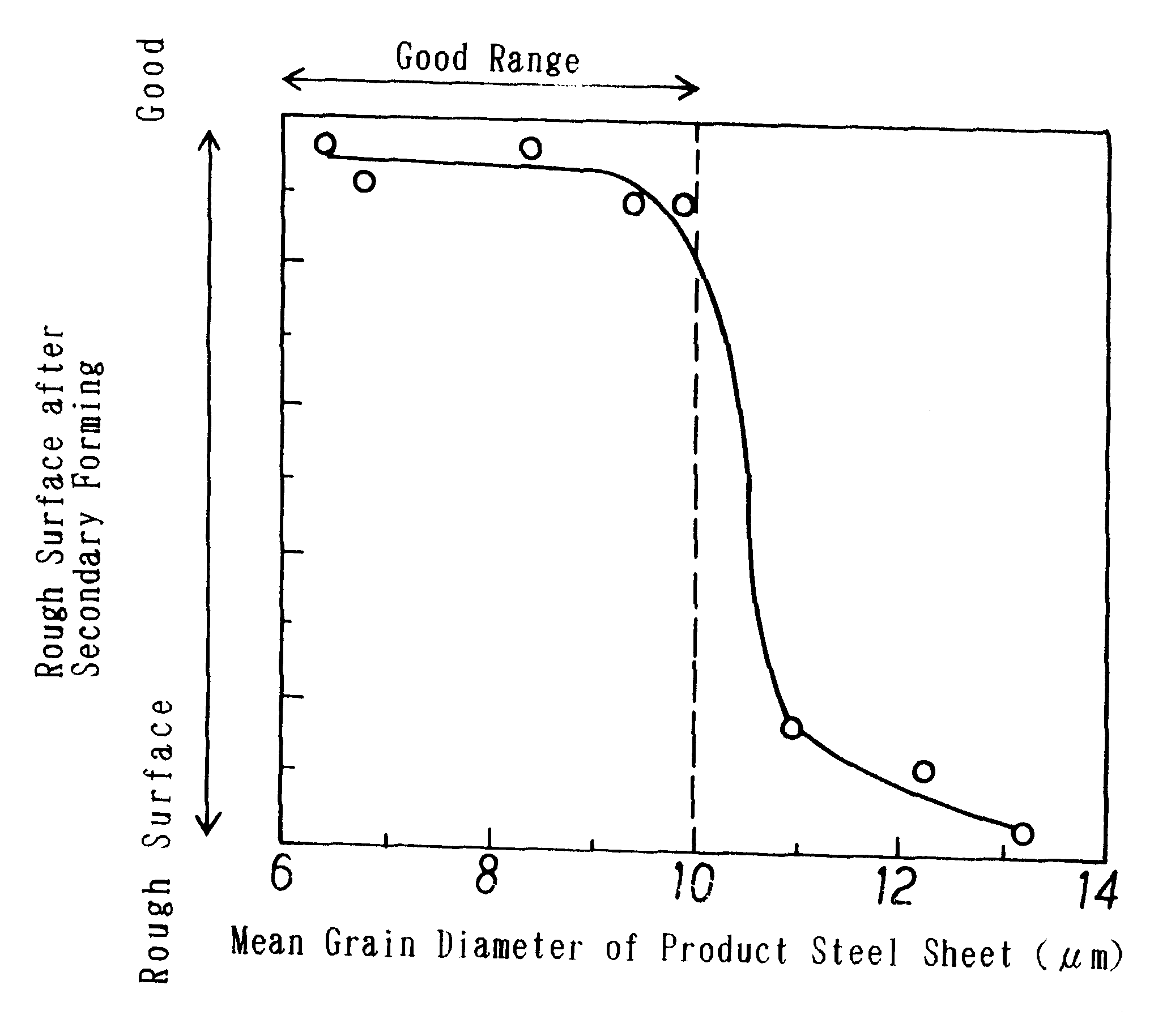
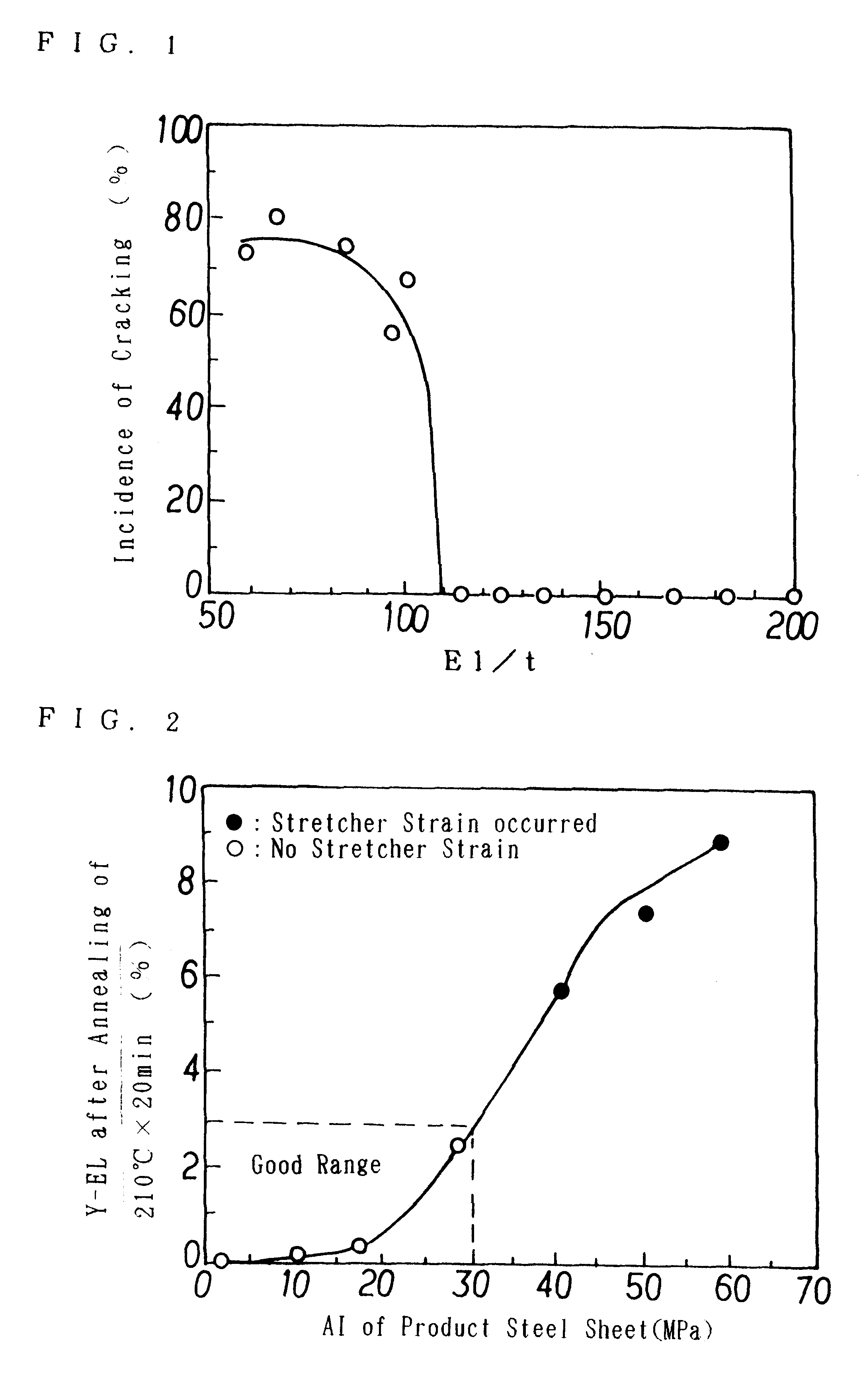
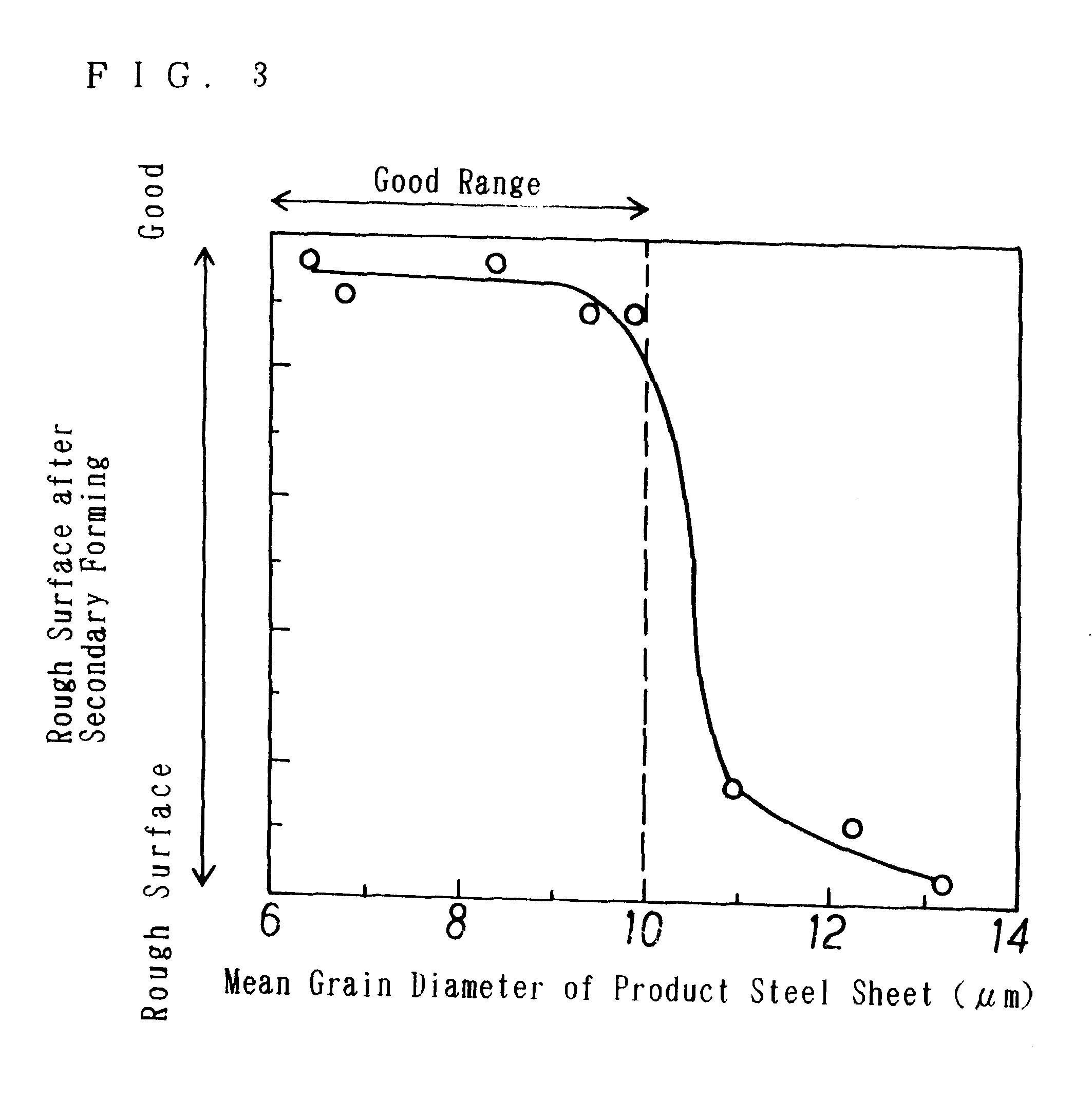
Test pieces were sampled from the rolling direction (L direction) and the cross direction (C direction) of thus obtained tin-plated steel sheets, and subjected to tests of total elongation EL, surface hardness HR30T, r-value, AI value and elongation at yield point (Y-EL) after an aging treatment corresponding to baking (210.degree. C..times.20 min), and the ratio of total elongation EL / t. In these tests, tensile test pieces of JIS No. 5 were used.

These steel sheets...

example 2

A series of cold-rolled steel sheets of 0.22 mm in finishing thickness were obtained by using a steel No. E shown in Table 1 and subjecting it to hot-rolling, cold-rolling, continues annealing, and secondary cold-rolling under manufacturing conditions shown in Table 4.

Subsequently, the steel sheets were subjected to continuous tin plating corresponding to #25 in a tin electroplating line of halogen type to give tinplates. Similar analyses to Example 1 were conducted on these product steel sheets. Table 5 demonstrates the results of the analyses. In this connection, as the hot-rolling, a rolling of pair cross type was conducted using a rolling mill having pair cross rolls at all stands, except under a manufacturing condition No. 2-13. As the cold-rolling, a rolling with concurrent use of cross-roll-type and shift roll type rolling using a rolling mill having roll-cross-type stands in the former stage was carried out, and crowns of cold-rolled steel sheets were controlled, except unde...

example 3

After taking out from a converter, a molten steel (300 ton) was subjected to decarburization using an RH vacuum degassing apparatus to control its composition to C=0.014 wt %, Si=0.01 wt %, Mn=0.25 wt %, P=0.010 wt %, S=0.005-0.009 wt % and to adjust the temperature of molten steel to a range from 1585 to 1615.degree. C. To this molten steel was added 0.2 to 0.8 kg / ton of Al to conduct preliminary deoxidation for 3 to 4 minutes to reduce the dissolved oxygen concentration in the molted steel to a range from 55 to 260 ppm. In this step, the Al concentration in the molten steel was 0.001 to 0.005 wt %. Then, to this molten steel was added 0.8 to 1.8 kg / ton of a 70 wt % Ti--Fe alloy to conduct Ti-deoxidation over 8 to 9 minutes. After adjusting the composition, a treatment was then carried out by adding to the molten steel a 30 wt % Ca-60 wt % Si alloy, or an additive obtained by adding metallic Ca, Fe, 5 to 15 wt % REM to the alloy, or an Fe-coated wire of 90 wt % Ca-5 wt % Ni alloy o...


PUM

PropertyMeasurementUnit
Temperatureaaaaaaaaaa

Abstract

The invention provides a can steel sheet having satisfactory surface appearance and having workability, appearance property after working and high yield that can meet demands on complicated can forming, and a manufacturing process thereof. To be more specific, according to the invention, a slab having a composition containing, in weight %, C: more than 0.005% and equal to or less than 0.1%, Mn: 0.05-1.0% is subjected to hot-rolling at a finishing temperature of 800 to 1000° C., to coiling at 500 to 750° C., to cold-rolling, followed by continuous annealing at a recrystallization temperature or higher and 800° C. or lower, and then to box annealing at a temperature higher than 500° C. and equal to or lower than 600° C. for 1 hr or longer. The steel sheet has preferably a structure containing ferrite as a principle phase and having a mean grain diameter of 10 mum or less and further containing 0.1-1% by weight of pearlite grains each having a grain diameter of 0.5-3 mum. To obtain satisfactory surface appearance, it is preferable that the steel contains: Ti: 0.015-0.10%, Al: 0.001-0.01%, and a total of 0.0005-0.01% of one or two members of Ca, REM, and S-5x((32/40)Ca+(32/140)REM) of 0.0014% or less.

Description

The present invention relates to a can steel sheet and a method for manufacturing the same. It relates to a can steel sheet advantageous for the application to three-piece cans, in particular, modified three-piece cans and method for manufacturing the same.Can containers can be roughly classified according to their parts and configurations as either two-piece cans each composed of a main body and a top lid or three-piece cans each composed of a main body, top and bottom lids. In such a three-piece can, its main body is connected by a process such as soldering, resin bonding, welding or the like.Recently, a demand has been increased for designed cans having more three-dimensional shapes than simply cylindrical cans, from the viewpoint of improving the design of cans. These circumstances are presented in, for example, a journal "THE CANMAKER February 1996, p32-37".These designed cans are mainly manufactured as three-piece cans, formed into a cylindrical shape, connected and then forme...

Claims


Application Information

Patent Timeline
IPC IPC(8): C22C38/04C22C38/00C22C38/06C22C38/14C21D8/02
CPCC21D8/0273C22C38/002C22C38/04C22C38/06C22C38/14C21D2211/005C21D2211/009C21D8/02
Inventor TOSAKA, AKIOARATANI, MASATOSHIFURUKIMI, OSAMUKUGUMINATO, HIDEOARATANI, MAKOTOMIKI, YUJI
Owner KAWASAKI STEEL CORP
Why Eureka
Try Eureka