
Slide zoom system of zoom camera lens

A zoom lens and lens technology, which is applied to the focusing device of a camera, the focusing device of a projector, a camera, etc., can solve the problems of decreased imaging contrast, inconsistent imaging, and reduced imaging clarity, so as to improve imaging contrast and imaging clarity. Consistent, avoids stray light effects

Inactive Publication Date: 2018-05-22
江苏慕藤光精密光学仪器有限公司
View PDF4 Cites 5 Cited by
  • Summary
  • Abstract
  • Description
  • Claims
  • Application Information

AI Technical Summary

Problems solved by technology

[0003] i. As a result, the center of each imaging is not at the same position, and the repeatability of zooming is poor, resulting in poor accuracy;
[0004] ii. Long-term use of clockwise and counterclockwise zoom results in inconsistencies in imaging, which will cause one side of the image to be clear and the other side to be unclear;
[0005] iii. Friction will produce friction dust, which falls on the surface inside the lens. Since the lens cannot be disassembled and cleaned, there will be noise in the imaging image, which will reduce the imaging clarity;
[0006] iv. Under the interaction force between the slider and the slider, sudden jamming is easy to occur, which affects the normal operation of the lens;
[0007] v. Long-term friction between the slider and the linear sleeve is likely to produce a shiny mirror surface. When the light passes through the inner cylinder of the optical system, a lot of stray light will appear, resulting in a decrease in imaging contrast.
[0008] vi. The precision of the zoom device in the zoom lens is high, so the linear sleeve and the curved sleeve are difficult to process with related equipment. They are usually made by manual grinding, and the human capital investment is too high
[0009] vii. Due to the friction transmission, the friction force is large, so a high-torque motor must be selected. However, in order to limit the shape and weight of the lens, the motor should not be too large. This problem can only be solved by increasing the current and increasing the power. consumes a lot;
[0010] viii. If the friction gap increases to a certain extent, the cross-section of the slider and the linear sleeve will lose the parallel relationship, and fatal sudden jams will easily occur during the up and down process, causing the lens to fail to work normally and must be disassembled for maintenance. Since the lens is installed in the airtight interior of the equipment and generally occurs at the user's site, it usually takes 3 days or more from the occurrence of the problem to the resolution of the problem, which seriously affects the production needs of the user and causes major economic losses;

Method used


Image

  • Slide zoom system of zoom camera lens
  • Slide zoom system of zoom camera lens

Examples


specific Embodiment example 1

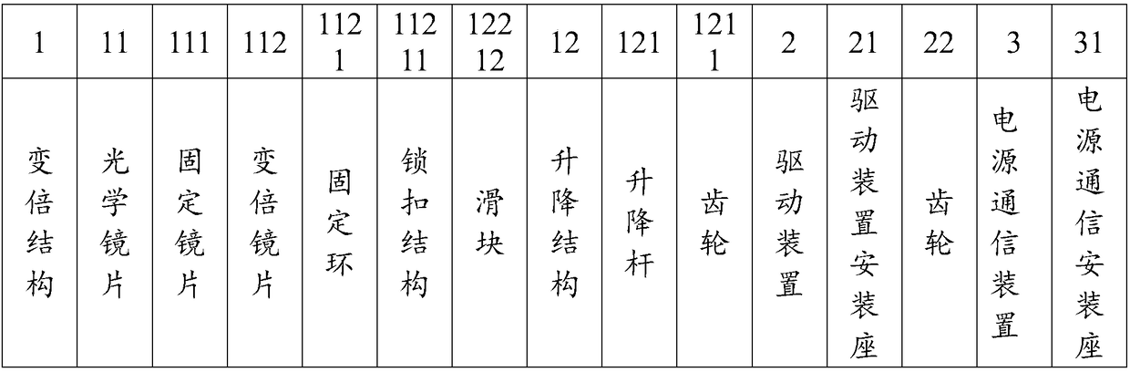
[0031] The sliding zoom system in the zoom lens mainly includes: a zoom structure 1, a drive device 2, and a power communication device 3. The zoom structure 1 includes an optical lens 11, a lifting structure 12, and the optical lens 11 includes a fixed frame that is fixed up and down. Glasses 111, two variable power lenses 112 on the same central axis between the upper and lower fixed lenses 111 and the distance between the two variable power lenses 112 are constant; the driving device 2 is fixed by the driving device fixing seat 21 and the power output end Connected with a gear 22, the driving device 2 is used to drive the lifting structure 12 and drive the zoom lens 112 to change the relative distance with the upper and lower fixed lenses 111; the power communication device 3 is fixed to the surrounding structure through the power communication fixing seat 31, and the power supply The communication device 3 is connected with an aviation plug as the energy supply of the relev...

specific Embodiment example 2

[0035] The sliding zoom system in the zoom lens mainly includes: a zoom structure 1, a drive device 2, and a power communication device 3. The zoom structure 1 includes an optical lens 11, a lifting structure 12, and the optical lens 11 includes a fixed frame that is fixed up and down. Glasses 111, two variable power lenses 112 on the same central axis between the upper and lower fixed lenses 111 and the distance between the two variable power lenses 112 are constant; the driving device 2 is fixed by the driving device fixing seat 21 and the power output end Connected with a gear 22, the driving device 2 is used to drive the lifting structure 12 and drive the zoom lens 112 to change the relative distance with the upper and lower fixed lenses 111; the power communication device 3 is fixed to the surrounding structure through the power communication fixing seat 31, and the power supply The communication device 3 is connected with an aviation plug as the energy supply of the relev...

specific Embodiment example 3

[0039] The sliding zoom system in the zoom lens mainly includes: a zoom structure 1, a drive device 2, and a power communication device 3. The zoom structure 1 includes an optical lens 11, a lifting structure 12, and the optical lens 11 includes a fixed frame that is fixed up and down. Glasses 111, two variable power lenses 112 on the same central axis between the upper and lower fixed lenses 111 and the distance between the two variable power lenses 112 are constant; the driving device 2 is fixed by the driving device fixing seat 21 and the power output end Connected with a gear 22, the driving device 2 is used to drive the lifting structure 12 and drive the zoom lens 112 to change the relative distance with the upper and lower fixed lenses 111; the power communication device 3 is fixed to the surrounding structure through the power communication fixing seat 31, and the power supply The communication device 3 is connected with an aviation plug as the energy supply of the relev...


PUM


Abstract

The invention relates to a slide zoom system of a zoom camera lens. The sliding zoom system includes a driving device, a zoom structure, and a power source communication device; the zoom structure includes optical lenses and a lifting structure; distances from zoom lenses to upper-lower fixed lenses are changed under the driving of the lifting structure, so that zooming operation can be realized;the lifting structure includes screw rod structures for lifting and lowering the zoom lenses, and slide rail devices for limiting the lifting and lowering rails of the zoom lenses; and one or more screw rods and slide rails may be adopted and do not influence one another. According to the sliding zoom system of the zoom camera lens, the sliding zoom structure can realize zooming by means of the screw rods and the slide rails so as to replace a traditional curve friction zooming mode, and therefore, friction gaps caused by friction, frictional powdered scraps, frictional smooth and bright mirror surface formation, lens sudden dead locking, and high temperature loss of the driving device which is caused by the manual grinding of a sleeve structure and excessive power can be avoided; and zoomrepeatability, imaging definition and imaging contrast can be improved, the accuracy of zooming and the normal operation of the production operation of a user can be ensured, and production costs andhuman input can be reduced.

Description

technical field [0001] The invention relates to the technical field of optical measuring instruments, in particular to a sliding zoom system in a zoom lens. Background technique [0002] With the advancement of science and technology and the improvement of measurement accuracy, at the same time, imaging tools have the advantages of rapidity, intuition, and accuracy, and zoom lenses are one of them. Zoom lenses are widely used in industrial inspection, automation, electronic communication, semiconductor, biomedical, scientific research and other fields. The zoom lens realizes the magnification and reduction of the target through the zoom device. The traditional zoom combination usually includes a curved sleeve with a curved chute on the outside, a linear sleeve placed inside the curved sleeve and processed with a straight chute, The fixed optical lens placed at both ends of the curved sleeve, the two variable power lenses placed in the linear sleeve, and the outside of the f...

Claims


Application Information

Patent Timeline
IPC IPC(8): G02B7/10G03B13/34
CPCG02B7/10G03B13/34
Inventor 童建
Owner 江苏慕藤光精密光学仪器有限公司
Features
  • Generate Ideas
  • Intellectual Property
  • Life Sciences
  • Materials
  • Tech Scout
  • Unparalleled Data Quality
  • Higher Quality Content
  • 60% Fewer Hallucinations
Learn More