CO2 enriched type two-phase absorbent with rapid and spontaneous layering

An enrichment, absorbent technology, applied in separation methods, dispersed particle separation, gas treatment, etc., can solve the problems of small load range, limited use, and high investment in phase separation, and achieve lower capture energy consumption and thermal stability. High, low volatility effect

Active Publication Date: 2018-05-29
ZHEJIANG UNIV
View PDF6 Cites 14 Cited by
  • Summary
  • Abstract
  • Description
  • Claims
  • Application Information

AI Technical Summary

Problems solved by technology

[0008] The two-phase absorbents disclosed above are effective in absorbing CO 2 The phase separation time of the upper and lower layers of the rear liquid phase is too long. The phase separation time is the most important parameter affecting the design of the phase separator. The longer the time, the larger the volume required for the equipment and the higher the investment
In addition, the existing two-phase absorbents spontaneously form a liquid-liquid two-phase phase separation load range is small, and the use is limited

Method used


Image

  • CO2 enriched type two-phase absorbent with rapid and spontaneous layering
  • CO2 enriched type two-phase absorbent with rapid and spontaneous layering
  • CO2 enriched type two-phase absorbent with rapid and spontaneous layering

Examples


Embodiment 1

[0029] Preparation of absorbent: Measure 50g of diethylaminoethanol (DEEA), 25g of ethanolamine (MEA) and 25g of deionized water, mix evenly, and prepare 50wt.% DEEA+25wt.%MEA+25wt.%H 2 Absorbent solution 100g of O, stand for later use.

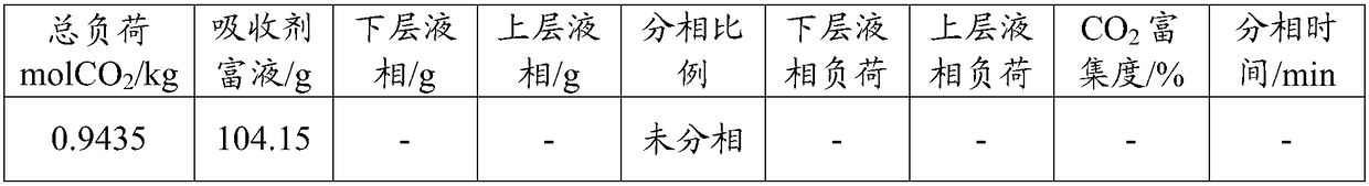
[0030] Then, absorb CO at a temperature of 40°C and normal pressure 2 , at different CO 2 Under load, phase separation ratio of absorbent rich liquid, CO 2 load distribution, CO 2 The enrichment degree and phase separation time are shown in Table 1 below.

[0031] The load in the table is defined as: CO absorbed per kg of amine and water in the absorbent 2 The amount of mol; the phase split ratio is defined as: absorbent rich liquid absorbs CO 2 After phase separation, the mass percentage of the lower liquid phase in the total liquid phase; CO 2 The degree of enrichment is defined as: CO absorbed in the lower liquid phase 2 % of total liquid phase absorbed CO 2 The mole percentage.

[0032] Table 1 is the different CO of the absorbent ...

Embodiment 2

[0037] Preparation of absorbent: Measure 50g of diethylaminoethanol (DEEA), 25g of hydroxyethylethylenediamine (AEEA) and 25g of deionized water, mix evenly, and prepare 50wt.% DEEA+25wt.% AEEA+25wt.% h 2 Absorbent solution 100g of O, stand for later use.

[0038] Then, absorb CO at a temperature of 40°C and normal pressure 2 , at different CO 2 Under load, phase separation ratio of absorbent rich liquid, CO 2 load distribution, CO 2 The enrichment degree and phase separation time are shown in Table 2 below.

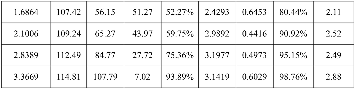
[0039] Table 2 is the different CO of the absorbent synthesized in embodiment 2 2 Performance parameters under load

[0040]

[0041] It can be seen from Table 2 that the phase separation load of the two-phase absorbent in this example to spontaneously form a liquid-liquid two-phase is 1.30-2.79mol CO 2 / kg absorbent.

Embodiment 3

[0043] Absorbent preparation: measure 50g diethylaminoethanol (DEEA), 20g hydroxyethylethylenediamine (AEEA), 5g piperazine (PZ) and 25g deionized water respectively, mix them evenly, and prepare 50wt.% DEEA+20wt .%AEEA+5wt.%PZ+25wt.%H 2 Absorbent solution 100g of O, stand for later use.

[0044] Then, absorb CO at a temperature of 40°C and normal pressure 2 , at different CO 2 Under load, phase separation ratio of absorbent rich liquid, CO 2 load distribution, CO 2 The enrichment degree and phase separation time are shown in Table 3 below.

[0045] Table 3 is the different CO of the absorbent synthesized in embodiment 3 2 Performance parameters under load

[0046]

[0047] It can be seen from Table 3 that the phase separation load of the two-phase absorbent in this example to spontaneously form a liquid-liquid two-phase is 1.70-3.33mol CO 2 / kg absorbent.


PUM


Abstract

The invention relates to a CO2 enriched type two-phase absorbent with rapid and spontaneous layering. The CO2 enriched type two-phase absorbent comprises the following components in percentage by mass: 30-60% of a phase splitting agent, 15-35% of an enriching agent, 0-25% of an accelerant and the balance of water, wherein the enriching agent is selected from one or more of cholamine, hydroxyethylethylenediamine, 3-amino-1-propanol, N-methyl-2-hydroxy ethylamine, ethyl oxyethylamine and isopropanolamine. By adopting the two-phase absorbent, the spontaneous phase splitting time of the two-phaseabsorbent is effectively shortened, and the phase splitting load range that the two-phase absorbent spontaneously forms liquid-liquid phases is increased.

Description

technical field [0001] The invention belongs to flue gas CO 2 The field of capture technology, specifically a rapid spontaneous stratification of CO 2 Rich two-phase absorbent. Background technique [0002] The rapid economic development has led to an increasing demand for energy, and a large amount of CO 2 Emissions cause the greenhouse effect, exacerbate global climate change, and pose a great threat to human survival. CO from fossil fuel consumption 2 Emissions account for more than 90% of total emissions, of which the power industry is the most important source of emissions, so CO 2 The focus of emission reduction is to control the flue gas CO of coal-fired power plants 2 emission. [0003] Coal-fired power plant flue gas CO 2 There are three main technical routes for capture: pre-combustion capture, oxygen-enriched combustion, and post-combustion capture, in which CO capture is captured after combustion 2 The technology has wide adaptability and is easier to be ...

Claims


Application Information

Patent Timeline
Patent Type & Authority Applications(China)
IPC IPC(8): B01D53/14
CPCB01D53/1475B01D2252/103B01D2252/202B01D2252/20421B01D2252/20447B01D2257/504
Inventor 王涛刘飞方梦祥徐燕洁王勤辉骆仲泱
Owner ZHEJIANG UNIV
Why Eureka
Try Eureka