A multi-cycle working fluid recovery flue gas waste heat oxygen-enriched combustion power generation integrated system
What is Al technical title?
Al technical title is built by PatSnap Al team. It summarizes the technical point description of the patent document.
A flue gas waste heat, oxygen-enriched combustion technology, applied in machines/engines, gas turbine devices, steam engine devices, etc., can solve the problems of toxic nitrogen oxide gas emissions, low LNG cold energy utilization efficiency, and inability to fully recover flue gas, etc. Achieve the effect of zero carbon emission, rational and efficient utilization, and reduction of energy consumption
Active Publication Date: 2019-07-19
HUAZHONG UNIV OF SCI & TECH
View PDF4 Cites 0 Cited by
Summary
Abstract
Description
Claims
Application Information
AI Technical Summary
This helps you quickly interpret patents by identifying the three key elements:
Problems solved by technology
Method used
Benefits of technology
Problems solved by technology
[0004] Aiming at the defects and deficiencies of the prior art, the present invention provides a multi-cycle working medium recovery flue gas waste heat oxygen-enriched combustion power generation integrated system, which solves the problem of the incomplete recovery of flue gas generated by power generation in the prior art and the utilization efficiency of LNG cold energy. Low and technical issues of nitrogen oxide toxic gas emissions
Method used
Image
Click on the blue label to locate the original text in one second.
Reading with bidirectional positioning of images and text.
Examples
Embodiment Construction
[0028] In order to make the object, technical solution and advantages of the present invention clearer, the present invention will be further described in detail below in conjunction with the accompanying drawings and embodiments. It should be understood that the specific embodiments described here are only used to explain the present invention, not to limit the present invention.
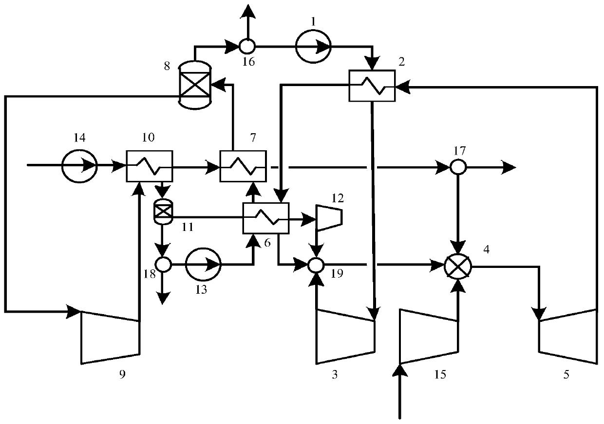
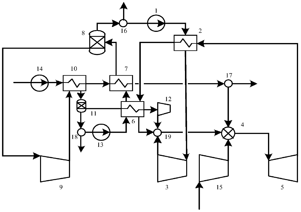
[0029] The present invention is an integrated system of multi-cycle working fluid recovery flue gas waste heat oxygen-enriched combustion power generation, including a water pump 1, a first heat exchanger 2, a steam turbine 3, a burner 4, a gas turbine 5, a multi-stream heat exchanger 6, and a second heat exchanger. Second heat exchanger 7, first gas-liquid separator 8, first compressor 9, third heat exchanger 10, second gas-liquid separator 11, second compressor 12, liquid CO 2 pump 13, LNG pump 14, third compressor 15, first flow divider 16, second flow divider 17, third flow divider 18 and fourt...
PUM
Abstract
The invention discloses a multi-circulating-medium flue gas waste heat recovery, oxygen-enriched combustion and power generation integrated system which comprises a water pump, a first heat exchanger,a steam turbine, a combustor, a gas turbine, a multi-flow heat exchanger, a second heat exchanger, a first gas-liquid separator, a first compressor, a third heat exchanger, a second gas-liquid separator, a second compressor, a liquid CO2 pump, an LNG pump, a third compressor, a first flow divider, a second flow divider, a third flow divider and a fourth flow divider. According to the multi-circulating-medium flue gas waste heat recovery, oxygen-enriched combustion and power generation integrated system disclosed by the invention, waste heat in flue gas can be sufficiently recovered by utilizing the difference among the boiling points of different working mediums; through the arrangement of the flow dividers in the multi-circulating-medium flue gas waste heat recovery, oxygen-enriched combustion and power generation integrated system, the composition ratio of three working mediums can be adjusted; and consequently, the amount of heat recovery can be improved by setting the optimum mixing ratio of the three working mediums, the system efficiency can be further optimized and improved at the optimum mixing ratio, waste heat from the combustion can be recovered to the greatest degree,and the zero-carbon emission of the multi-circulating-medium flue gas waste heat recovery, oxygen-enriched combustion and power generation integrated system can be achieved when the system power consumption is lowered.
Description
technical field [0001] The invention relates to an integrated power generation system for recovering flue gas waste heat in the electric power industry, and more specifically, to an integrated system for recovering flue gas waste heat and oxygen-enriched combustion power generation with multi-cycle working fluid. Background technique [0002] At present, climate warming has become a global problem, and CO 2 It is the gas with the greatest impact on climate change, and its warming effect accounts for 63% of the total warming effect of all greenhouse gases. Under the current severe environmental protection situation, the call for energy saving and emission reduction is becoming stronger and stronger, and countries all over the world are also seeking technologies to reduce CO 2 emission. Carbon capture and storage technology (Carbon Capture and Storage, CCS) is currently recognized as the most promising CO 2 One of the means of emission reduction, and oxy-fuel combustion tec...
Claims
Application Information
Patent Timeline
Application Date:The date an application was filed.
Publication Date:The date a patent or application was officially published.
First Publication Date:The earliest publication date of a patent with the same application number.
Issue Date:Publication date of the patent grant document.
PCT Entry Date:The Entry date of PCT National Phase.
Estimated Expiry Date:The statutory expiry date of a patent right according to the Patent Law, and it is the longest term of protection that the patent right can achieve without the termination of the patent right due to other reasons(Term extension factor has been taken into account ).
Invalid Date:Actual expiry date is based on effective date or publication date of legal transaction data of invalid patent.