
In-situ thermal desorption repair system and method for polluted soil

A technology for contaminated soil and remediation system, which is applied in the field of in-situ thermal desorption remediation system for contaminated soil, which can solve the problems of poor semi-volatile organic compound removal effect, uneven heating effect distribution, long repair time, etc., and expand the applicable area range, reduction in additional energy consumption and costs, and reduction in restoration costs

Pending Publication Date: 2018-06-05
YONKER ENVIRONMENTAL PROTECTION
View PDF11 Cites 47 Cited by
  • Summary
  • Abstract
  • Description
  • Claims
  • Application Information

AI Technical Summary

Problems solved by technology

[0011] The heating effect of the traditional resistance heating method is unevenly distributed, and due to the limitation of temperature, the removal effect of semi-volatile organic compounds with high boiling point is not good, resulting in poor local effect, high energy consumption and long repair time

Method used


Image

  • In-situ thermal desorption repair system and method for polluted soil
  • In-situ thermal desorption repair system and method for polluted soil
  • In-situ thermal desorption repair system and method for polluted soil

Examples


Embodiment

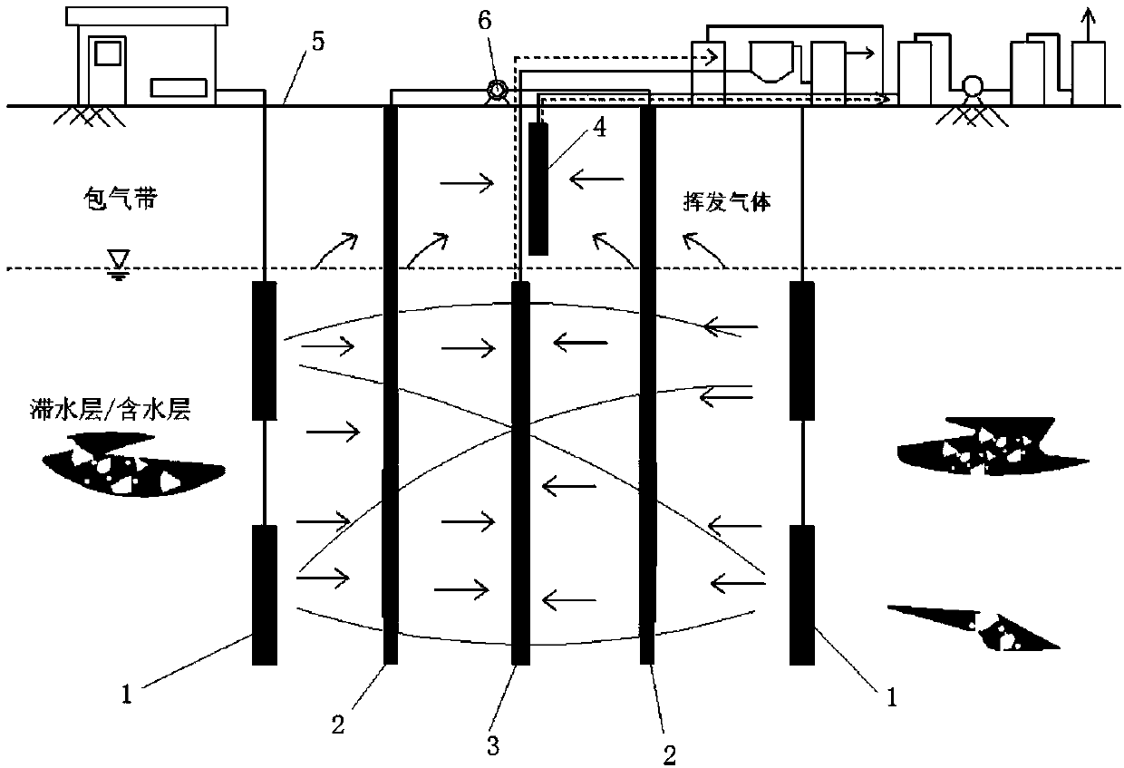
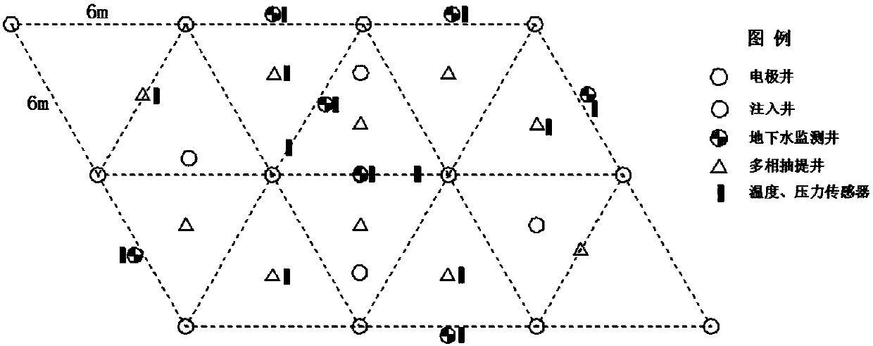
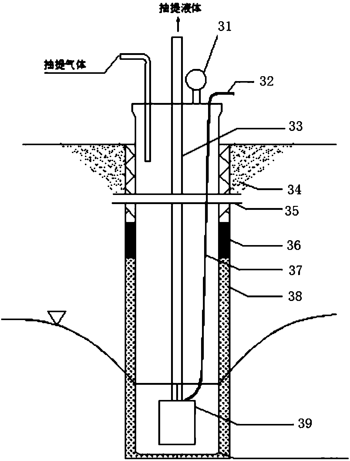
[0043] Such as figure 1As shown, an in-situ thermal desorption remediation system for contaminated soil includes several in-situ heating electrodes arranged in the soil, several injection wells, several extraction wells, several groundwater monitoring wells, and electrode power control and adjustment facilities on the ground , in-situ temperature and pressure monitoring facilities, sewage treatment facilities and waste gas treatment facilities; the extraction well is equipped with an extraction device, which is connected to the sewage treatment facility and waste gas treatment facility; the injection well is equipped with an injection device, and the injection device is connected to the The storage box for the leaching reagent; the in-situ heating electrode is connected to the electrode power control and adjustment facility, which is arranged in a regular triangle or a regular hexagon.

[0044] The repair system also includes a covering barrier layer, which is arranged above t...


PUM


Abstract

The invention relates to an in-situ thermal desorption repair system and a method for polluted soil. The system comprises a plurality of in-situ heating electrodes, a plurality of injection wells, a plurality of extraction wells, a plurality of groundwater monitoring wells, electrode power control and adjustment facilities, in-situ temperature and pressure monitoring facilities, sewage treatment facilities and waste gas treatment facilities; each extraction well is provided with an extraction device which is connected with a sewage treatment facility and a waste gas treatment facility; each injection well is internally provided with an injection device which is connected with a material storage box containing a leaching reagent; and the in-situ heating electrodes are arranged in a regulartriangular or regular hexagonal manner. Compared with the prior art, after the leaching reagent is added to dissolve pollutants, the solubility of the pollutants is increased, the speed of the pollutants entering a liquid phase from a soil adsorption phase is increased, and the removal rate and removal efficiency of the pollutants are improved.

Description

technical field [0001] The invention relates to the technical field of soil remediation, in particular to an in-situ thermal desorption remediation system and method for polluted soil. Background technique [0002] The in-situ thermal desorption technology is an important technology in the in-situ remediation technology of polluted soil. Its main principle is to heat the polluted soil to above the boiling point of the target pollutant in situ, so as to promote the gasification and volatilization of the pollutant, so that the target pollution Separation and removal of substances from soil particles. The thermal desorption process can cause physical and chemical changes such as volatilization and cracking of organic compounds in the soil. When the pollutants are converted into gaseous state, their fluidity will be greatly improved, and the volatilized gaseous products will be purified after being collected and captured. [0003] In situ thermal desorption technology is espec...

Claims


Application Information

Patent Timeline
IPC IPC(8): B09C1/06C02F1/02C02F103/06
CPCC02F1/02B09C1/002B09C1/005B09C1/062B09C2101/00C02F2103/06
Inventor 罗启仕杨仔赵秀红斯克诚周玉强吴晴雯
Owner YONKER ENVIRONMENTAL PROTECTION
Learn More