Integrated drug screening and staining method based on micro-fluidic chip
The technology of a microfluidic chip and a dyeing method is applied in the field of integrated drug screening and dyeing based on the microfluidic chip, and can solve the problems of a large amount of consumption and complicated and complicated operation steps.
- Summary
- Abstract
- Description
- Claims
- Application Information
AI Technical Summary
Problems solved by technology
Method used
Image
Examples
Embodiment 1
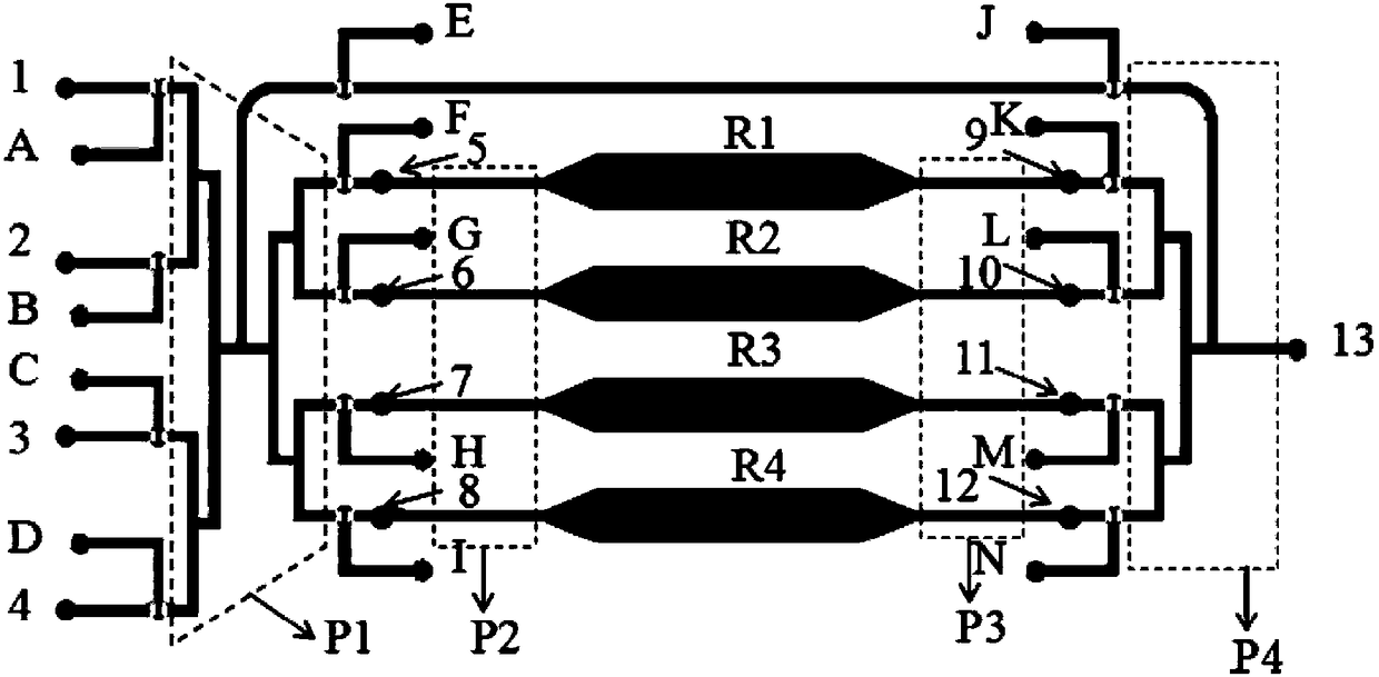
[0086] An integrated drug screening and dyeing method based on a microfluidic chip. The integrated drug screening and dyeing microfluidic chip is composed of an upper layer, a lower layer, and a bottom layer, which are arranged in series in series, wherein: the upper layer is a liquid circuit control layer, the lower layer is the gas circuit control layer, and the bottom is a blank glass bottom plate;
[0087] The liquid path control layer is specifically provided with the following structure:
[0088] ——Cell fluorescence dyeing inlet: located at the most upstream of the entire fluid circuit control layer;
[0089] ——Fluorescence dyeing injection channel area P1: arranged between the cell fluorescence dyeing injection port and the cell injection channel area P2 for communication between the two;
[0090] ——Cell sampling port: it is provided with at least two, and each cell sampling port is set on one of the channels in the cell sampling channel area P2, and each channel in th...
Embodiment 2
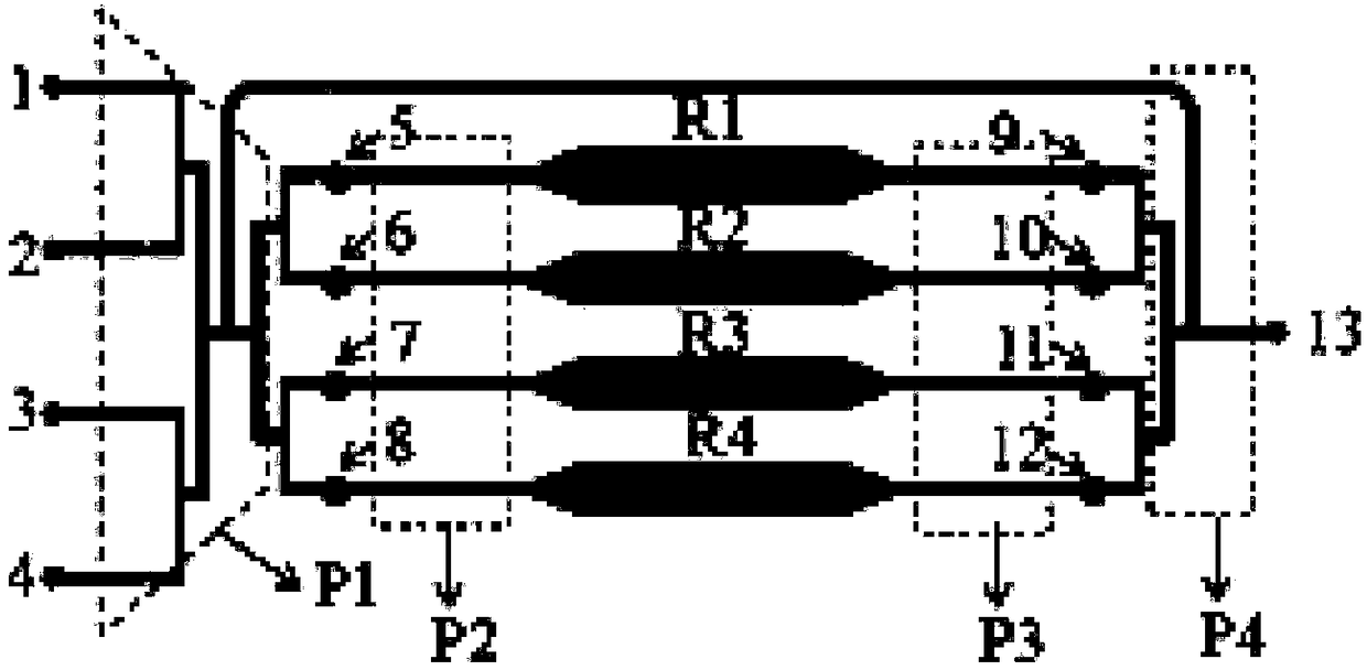
[0145] An integrated drug screening and dyeing method based on a microfluidic chip. The integrated drug screening and dyeing microfluidic chip is composed of an upper layer, a lower layer, and a bottom layer, which are arranged in series in series, wherein: the upper layer is a liquid circuit control layer, the lower layer is the gas circuit control layer, and the bottom is a blank glass bottom plate;
[0146] The liquid path control layer is specifically provided with the following structure:
[0147] ——Cell fluorescence dyeing inlet: located at the most upstream of the entire fluid circuit control layer;
[0148] ——Fluorescence dyeing injection channel area P1: arranged between the cell fluorescence dyeing injection port and the cell injection channel area P2 for communication between the two;
[0149] ——Cell sampling port: it is provided with at least two, and each cell sampling port is set on one of the channels in the cell sampling channel area P2, and each channel in th...
Embodiment 3
[0190] The SU-8 template with channel part protrusions was prepared by photolithography and etching. The upper and lower structures of the chip were respectively composed of two SU-8 template anti-mold PDMS; Make PDMS easy to peel off the bottom surface of the template; PDMS and initiator are mixed evenly at a volume ratio of 10:1, poured on the upper and lower structure SU-8 templates of the chip respectively, and cured in an oven at 80°C for 40 minutes, and the PDMS and the upper SU-8 template of the chip are peeled off. Obtain a PDMS chip with a structure; treat the upper layer of the chip with the structure with the lower layer of the chip without the structure on the SU-8 template for 2 minutes, heat bake at 80°C for 1 hour, and seal irreversibly; seal the above The PDMS chip was peeled off from the SU-8 template of the underlying structure, treated with oxygen plasma for 2 minutes with a clean blank glass slide, and then baked at 80°C for 1 hour for irreversible sealing, ...
PUM
 Abstract
Description
Claims
Application Information
 - R&D
- Intellectual Property
- Life Sciences
- Materials
- Tech Scout
- Unparalleled Data Quality
- Higher Quality Content
- 60% Fewer Hallucinations
Browse by: Latest US Patents, China's latest patents, Technical Efficacy Thesaurus, Application Domain, Technology Topic, Popular Technical Reports.
© 2025 PatSnap. All rights reserved.Legal|Privacy policy|Modern Slavery Act Transparency Statement|Sitemap|About US| Contact US: help@patsnap.com


