A vertical axis wind turbine blade assembly and synthetic jet control method thereof

A technology of wind turbine blades and synthetic jets, which is applied in the control of wind turbines, wind turbines at right angles to the wind direction, wind turbines, etc., can solve the periodic change of the blade angle of attack, the decline of system reliability, and the complex flow field structure, etc. problem, to achieve the effect of improving aerodynamic performance, reducing wake strength, and low power consumption

Active Publication Date: 2019-11-01
UNIV OF SHANGHAI FOR SCI & TECH
View PDF4 Cites 0 Cited by
  • Summary
  • Abstract
  • Description
  • Claims
  • Application Information

AI Technical Summary

Problems solved by technology

On the contrary, the vertical axis wind turbine has the following disadvantages: ① Low efficiency ② Difficulty in self-starting ③ The angle of attack of the blade changes greatly periodically
[0005] However, the blowing and suction flow control scheme in the prior art still has disadvantages: additional air sources, pipelines and control valves are required, resulting in a large increase in extra weight and a decrease in system reliability due to complex structures
However, the angle of attack of the blades of the vertical axis wind turbine varies greatly periodically with the azimuth angle. The traditional synthetic jet flow control technology is no longer applicable to the vertical axis wind turbine. It is necessary to design a synthetic jet actuator whose output power varies with the blade angle of attack. Control Method

Method used


Image

  • A vertical axis wind turbine blade assembly and synthetic jet control method thereof
  • A vertical axis wind turbine blade assembly and synthetic jet control method thereof
  • A vertical axis wind turbine blade assembly and synthetic jet control method thereof

Examples


Embodiment 1

[0081] Figure 7 is the Lamuda type synthetic jet control function and its schematic diagram in the embodiment of the present invention.

[0082] Such as Figure 7 shown in the figure

[0083]

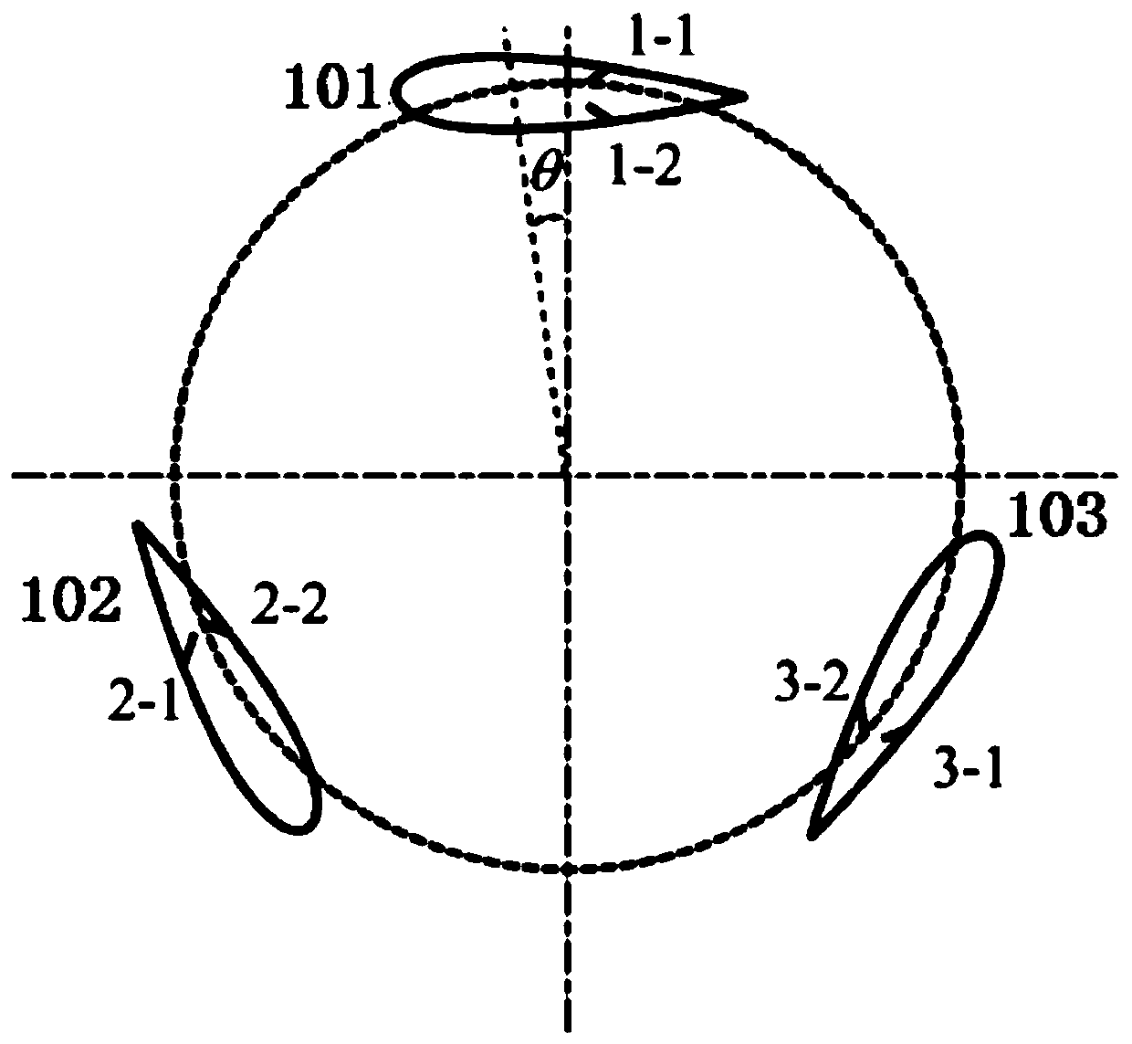
[0084] When the jet hole 106 is on the pressure side of the blade, the jet is closed, and when it is on the suction side, the jet is turned on, and the fluid is blown / absorbed at a certain working frequency; the amplitude of the piezoelectric film can be controlled, and the excitation frequency of the exciter can also be controlled to make the jet blowing coefficient C μ As the effective angle of attack of the blade increases, the jet blowing coefficient C at zero angle of attack μ is 0. combine figure 1 , the initial position of jet hole 1-1 is on the pressure surface of the blade, and the initial position of jet hole 1-2 is on the suction surface of the blade, so jet hole 1-2 should open the jet, and the jet blowing coefficient C μ size should vary with Figure 7 The Lamuda co...

Embodiment 2

[0086] Figure 8 is the piecewise linear synthetic jet control function and its schematic diagram in the embodiment of the present invention.

[0087] Such as Figure 8 shown in the figure

[0088] When the jet hole 106 is on the pressure side of the blade, the jet is closed, and when it is on the suction side, the jet is turned on, and the fluid is blown / absorbed at a certain working frequency; the amplitude of the piezoelectric film can be controlled, and the excitation frequency of the exciter can also be controlled, so that the jet blowing coefficient can be adjusted accordingly. The effective angle of attack of the blade increases, and the blowing coefficient of the jet is 0 when the angle of attack is zero. combine figure 1 , the starting position of jet hole 1-1 is on the pressure surface of the blade, and the starting position of jet hole 1-2 is on the suction side of the blade, so jet hole 1-2 should open the jet, and the jet blowing coefficient should vary with ...

Embodiment 3

[0090] Figure 9 is the Sin-type synthetic jet control function and its schematic diagram in the embodiment of the present invention.

[0091] Such as Figure 9 shown in the figure

[0092] When the jet hole 106 is on the pressure side of the blade, the jet is closed, and when it is on the suction side, the jet is turned on, and the fluid is blown / absorbed at a certain working frequency; the amplitude of the piezoelectric film can be controlled, and the excitation frequency of the exciter can also be controlled, so that the jet blowing coefficient can be adjusted accordingly. The effective angle of attack of the blade increases, and the blowing coefficient of the jet is 0 when the angle of attack is zero. combine figure 1 , the starting position of jet hole 1-1 is on the pressure surface of the blade, and the starting position of jet hole 1-2 is on the suction side of the blade, so jet hole 1-2 should open the jet, and the jet blowing coefficient should vary with Figure...


PUM


Abstract

The invention discloses a vertical axis wind turbine blade module and a synthesized jet control method thereof. The vertical axis wind turbine blade module is arranged on a base of a vertical axis wind turbine, and comprises multiple blade bodies, synthesized jet exciters and multiple jet holes, wherein the upper and lower ends of each blade body are fixed on a rotating shaft of the vertical axiswind turbine through fixed rod pieces; the synthesized jet exciters are uniformly and serially arranged in the blade bodies in the blade height directions of the blade bodies; the multiple jet holes are formed in the tail edges of the blade bodies; the synthesized jet exciters comprise shells, piezoelectric films, jet channels, piezoelectric drivers and control boxes, wherein the shells are squares, and are provided with upper openings and the lower openings; the piezoelectric films are squares, and cover the lower openings; the jet channels communicate with the upper openings; the piezoelectric drivers are arranged below the piezoelectric films, and are driven by rectangular pulse signals to generate a reverse piezoelectric effect so as to drive the square piezoelectric films to periodically vibrate up and down; and the control boxes are arranged above rotating shafts, are electrically connected with the piezoelectric drivers, and are used for inputting the rectangular pulse signals to the piezoelectric drivers.

Description

technical field [0001] The invention belongs to the field of structural control and electrical control, and in particular relates to a vertical axis wind turbine blade assembly and a synthetic jet control method thereof. Background technique [0002] Under the general trend of environmental protection, wind energy utilization technology has attracted widespread attention from various countries. As a wind energy utilization device, the vertical axis wind turbine converts wind energy into electrical energy. Compared with horizontal axis wind turbines, vertical axis wind turbines have the following advantages: ① No need to face the wind; ② Lower operating noise; ③ Lower cost; ④ More stable operation. On the contrary, the vertical axis wind turbine has the following disadvantages: ① low efficiency; ② difficult self-starting; ③ large periodic changes in the blade angle of attack; ④ interaction between blade wake vortex, rotor shaft wake vortex and blade tip vortex, resulting in e...

Claims


Application Information

Patent Timeline
Patent Type & Authority Patents(China)
IPC IPC(8): F03D3/06F03D7/06
CPCF03D3/061F03D3/062F03D7/06F05B2220/709F05B2240/212F05B2240/30Y02E10/74
Inventor 李春朱海天吴柏慧郝文星丁勤卫余万王渊博刘宇航向斌韩志伟
Owner UNIV OF SHANGHAI FOR SCI & TECH
Why Eureka
Try Eureka