Fluid dynamic annular space cavitation device

A fluid power and cavitation technology, applied in the direction of production fluid, wellbore/well components, earthwork drilling and production, etc., can solve the problems that affect the full production of crude oil, limited operation effect, corrosion of construction equipment and pipe strings, etc., and achieve the goal of overcoming cavitation The effect of cavitation is not good or even cavitation is not good, the effect lasts for a long time, and the radiation range expands

Inactive Publication Date: 2018-06-15
北京漫海能源科技有限公司
View PDF2 Cites 2 Cited by
  • Summary
  • Abstract
  • Description
  • Claims
  • Application Information

AI Technical Summary

Problems solved by technology

(2) Serious pollution to oil well formation
If the fracturing fluid for hydraulic fracturing is improperly selected, it may cause formation clay minerals to swell, crude oil to emulsify, and precipitation due to incompatibility with formation water, etc., which will damage the original physical properties of the formation; for acid fracturing, the acid will Harm to the formation, acid may also corrode construction equipment and pipe strings
At the same time, the fracturing operation is a high-pressure operation, and various acidification agents may pose a serious threat to the construction personnel and the surrounding ecological environment during the construction process.
(3) Water fracturing is extremely destructive to oil wells and formations. If fracturing is not done properly, it may cause severe consequences of violent water flooding and reactive water injection of oil wells, and may also depress the top of adjacent aquifers or gas-bearing layers.
(4) The artificial fractures or channels created by hydraulic fracturing aggravate the heterogeneity of the reservoir, seriously affect the full production of crude oil in the reservoir, which itself may have an adverse effect on reservoir development
[0006] Ultrasonic cavitation has the following disadvantages: (1) This technology can only be used for unblocking the formation near the wellbore. The cavitation effect of the liquid medium requires the ultrasonic wave to reach a certain intensity. The higher the ultrasonic power, the better the unblocking effect. However, the attenuation speed of the ultrasonic wave is extremely fast. Some studies have shown that the ultrasonic intensity at the well wall has been attenuated to 45% of the sound source, and the ultrasonic intensity at the radius of the geometric model of the void medium is 1 meter attenuated to 10% at the well wall.
Therefore, the ultrasonic cavitation effect is limited to the formation near the wellbore, and the maximum operating radius is only 15 meters, so the operating effect is limited
(2) The ultrasonic cavitation operation area is in a non-flowing state, and the cavitation area around its converter is limited. With the increase of external pressure, no new cavitation will be formed under the high pressure of deep well static water
In deep wells and extended pipelines, cavitation effects may not be obtained under high external hydrostatic pressure
(3) Limited by the processing time, the operation effect is limited
The cumulative ultrasonic treatment time is the key to the effect of ultrasonic cavitation, but a lot of practice has proved that after the cumulative ultrasonic treatment time exceeds 1 hour, the increase in its effect will no longer be obvious; the higher the ultrasonic frequency, the greater the attenuation during the propagation process, which will also affect its effect. job effect
(4) The technical supporting equipment is complicated, the cost is high, and the requirements for the working environment are also high
(5) This technology is not suitable for oil wells and horizontal wells with an inclination greater than 45 degrees

Method used


Image

  • Fluid dynamic annular space cavitation device
  • Fluid dynamic annular space cavitation device
  • Fluid dynamic annular space cavitation device

Examples


Embodiment 1

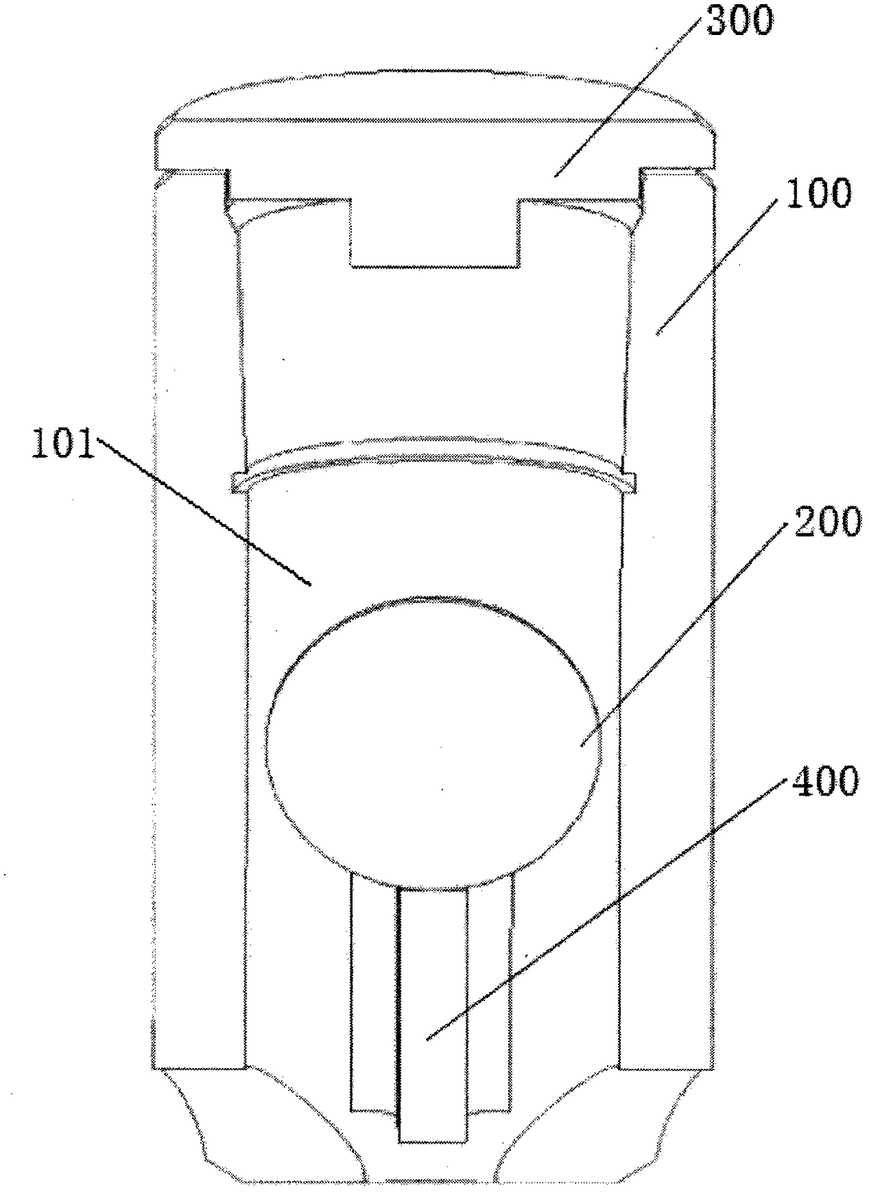
[0034] Such as figure 1 As shown: the hydrodynamic annular space cavitation device provided by Embodiment 1 of the present invention includes a cylindrical shell 100, a spherical dynamic body 200, a stop plate 300 and a bracket 400, and a working area is set inside the cylindrical shell 100 101, the spherical power body 200 is set in the working area 101 in the cylindrical housing 100, and a fluid (water) circulation is formed between the outer wall of the spherical power body 200 and the inner wall of the cylindrical housing 100 channel (not shown in the figure), and cavitate the fluid flowing through the channel, the stop plate 300 is arranged on the top of the cylindrical housing 100, and is used to prevent the spherical power body 200 from The upper part of the cylindrical housing 100 is protruded, so that the spherical power body 200 works in the working area 101 in the cylindrical housing 100, and the stop plate 300 is provided with a water hole, and the bracket 400 It ...

Embodiment 2

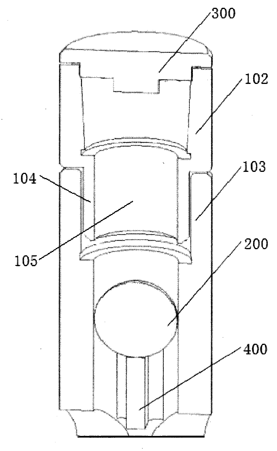
[0037] Such as figure 2 As shown, the difference between the hydrodynamic annulus cavitation device provided by Embodiment 2 of the present invention and Embodiment 1 is that: the cylindrical casing 100 includes an upper cylindrical casing 102 and a lower cylindrical casing 103, and the upper cylindrical casing 100 The lower end of the cylindrical housing 102 is arranged inside the upper end of the lower cylindrical housing 103, and the lower end of the upper cylindrical housing 102 is screwed to the upper end of the lower cylindrical housing 103 to form a tight fit; in order to meet different situations It is manufactured according to the oil well depth and reservoir structure, and can be adjusted according to different construction conditions.

[0038] The lower end of the upper cylindrical housing 102 is provided with an extension 104 extending downwards, the shape of the extension 104 is cylindrical, and the inside of the extension 104 is provided with a first through hol...

Embodiment 3

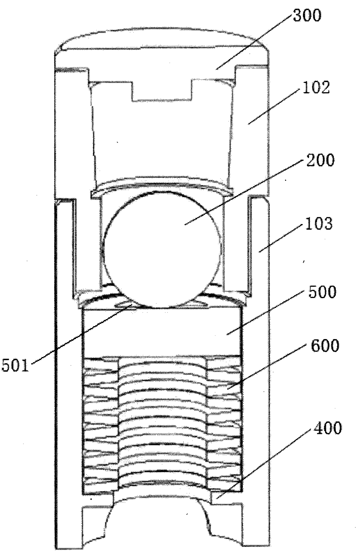
[0041] The difference between the hydrodynamic annulus cavitation device provided by Embodiment 3 of the present invention and Embodiment 2 is that the body dynamic annular cavitation device of the present invention further includes a backing plate 500 and a plurality of disc springs 600, and the backing plate 500 The shape is cylindrical, the backing plate 500 is arranged in the lower cylindrical housing 103, the spherical power body 200 is arranged on the backing plate 500, and the backing plate 500 is provided with a first passage for fluid to pass through. Two through holes 501 , and the inner diameter of the second through hole 501 provided on the backing plate 500 is smaller than the outer diameter of the spherical power body 200 .

[0042] A plurality of disc springs 600 are disposed below the backing plate 500 and above the bracket 400 . The setting of the backing plate 500 and multiple disc springs 600 above can play a buffering role, reduce the wear on the spherical ...


PUM


Abstract

The invention relates to a fluid dynamic annular space cavitation device. The fluid dynamic annular space cavitation device comprises a cylindrical shell body, a spherical dynamic body, a stop plate and a bracket; the cylindrical shell body is internally provided with a working area, and the spherical dynamic body is disposed in the working area in the cylindrical shell body; a channel for fluid flowing is formed between the outer wall of the spherical dynamic body and the inner wall of the cylindrical shell body, and fluid flowing through the channel is subjected to cavitation; the stop plateis disposed on the top of the cylindrical shell body and used for preventing the spherical dynamic body from escaping from the upper part of the cylindrical shell body, so that the spherical dynamicbody is operated within the working area in the cylindrical shell body; and the bracket is disposed at the inner bottom of the cylindrical shell body for preventing the spherical dynamic body from coming out of the lower portion of the cylindrical shell body. The fluid dynamic annular space cavitation device has the beneficial effects of small volume, wide application range and safety and reliability.

Description

technical field [0001] The invention relates to a hydrodynamic annular gap cavitation device. Background technique [0002] In the oilfields developed and produced in the early stage, the comprehensive recovery rate is generally low due to factors such as formation pressure attenuation and oil layer plugging. At present, there are two common technologies for enhancing oil recovery, one is hydraulic fracturing technology, and the other is ultrasonic cavitation technology. [0003] Hydraulic fracturing technology is an enhanced oil recovery technology that injects fracturing fluid into the oil layer to create fractures and change the liquid state of the oil flow. This technology is an important technical means for the development of oil and gas wells, especially low-permeability oil and gas, and is currently widely used in various oil fields across the country. The technical principle is to inject liquid (water, fracturing fluid) into the oil well at a displacement exceeding ...

Claims


Application Information

Patent Timeline
Patent Type & Authority Applications(China)
IPC IPC(8): E21B43/16E21B43/25
Inventor 马英
Owner 北京漫海能源科技有限公司
Why Eureka
Try Eureka