Firing system gradient combustion self-denitration technological method

A process method and gradient technology, applied in combustion methods, combustion control, and fuel supply regulation, can solve the problems of high excess air coefficient, difficulty in suppressing NOx, and poor denitrification effect in lean-oxygen combustion zone, and achieve improved self-denitrification. Efficiency, extended residence time, good reliability

Active Publication Date: 2018-06-15
TIANJIN CEMENT IND DESIGN & RES INST
View PDF4 Cites 17 Cited by
  • Summary
  • Abstract
  • Description
  • Claims
  • Application Information

AI Technical Summary

Problems solved by technology

The fuel staged combustion technology uses staged feeding of fuel into the calciner to form an oxygen-poor combustion area in the cone of the calciner, which can effectively reduce the NOx in the flue gas exiting the rotary kiln, but it is difficult to suppress the NOx produced by the combustion of the calciner fuel itself
The air staged combustion technology utilizes the staged feeding of the tertiary air into the furnace to form an oxygen-poor combustion zone in the calciner column section, which can suppress the NOx produced by the combustion of the calciner fuel itself, but the excess air coefficient of the formed oxygen-depleted combustion zone is still high. The overall denitrification effect is not good

Method used


Image

  • Firing system gradient combustion self-denitration technological method

Examples


Embodiment 1

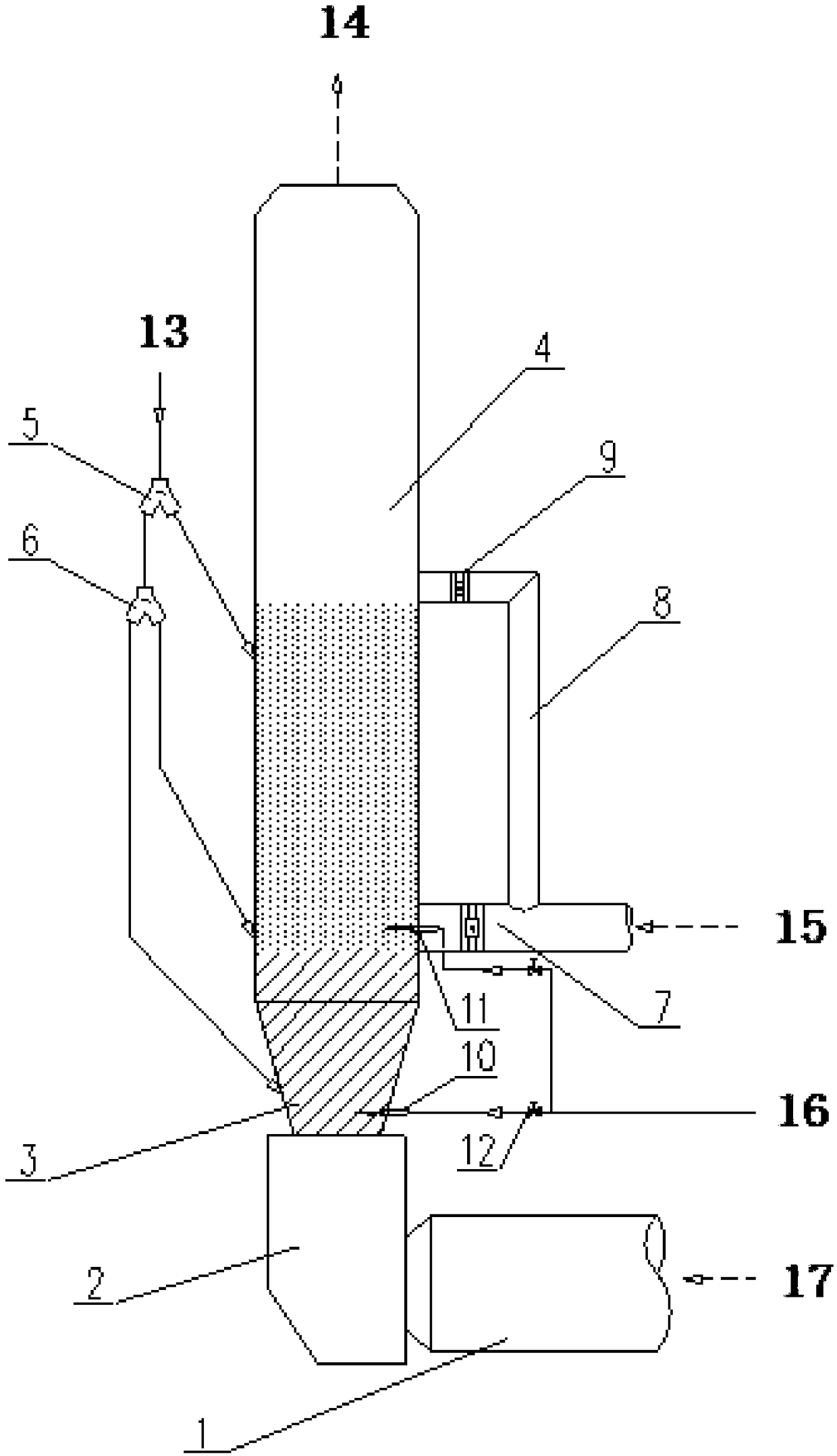
[0031] A gradient combustion self-denitration process method for a firing system, the technical scheme of which is: the flue gas from the rotary kiln passes through the rotary kiln 1 and the smoke chamber 2 and then enters the calciner cone 3 and the calciner column 4, and the materials entering the calciner pass through the material distribution The valve 5 and the distribution valve 6 are fed into the calciner in three stages, wherein the first-stage material pipe is connected to the calciner cone 3, the second-stage material pipe is connected to the lower part of the calciner column 4, and the third-stage material pipe is connected to the decomposition furnace. Furnace column body 4 middle parts. Through the opening control of the upper distributing valve 5 of the calciner and the lower distributing valve 6 of the calciner, the ratio of distributing materials in the material pipes of each level can be adjusted in any proportion. The tertiary air duct for entering the furnac...


PUM


Abstract

The invention relates to a firing system gradient combustion self-denitration technological method, and belongs to the technical field of cement industry flue gas denitration. According to the firingsystem gradient combustion self-denitration technological method, a gradient combustion environment with an extreme oxygen deficient area-oxygen deficient combustion area-oxygen enrichment burnout area is formed in a decomposing furnace; the gradient combustion environment is realized through classified feeding of decomposing furnace inlet fuel, tertiary air and decomposing furnace inlet materials; a furnace inlet tertiary air hose is divided into an upper branched pipe and a lower branched pipe, the tertiary air lower branched pipe is fed in from the lower portion of a decomposing furnace cylinder, and the upper branched pipe is fed in from the middle of the decomposing furnace cylinder; the decomposing furnace inlet fuel is divided into two layers and is further fed into the furnace, thelower layer of the fuel is fed in from a decomposing furnace cone, and the upper layer of the fuel is fed in from the decomposing furnace cylinder; the extreme oxygen deficient area refers to the decomposing furnace area located below the tertiary air lower branched pipe; the oxygen deficient combustion area refers to the area located between the tertiary air upper branched pipe and the tertiaryair lower branched pipe; and the oxygen enrichment burnout area refers to the decomposing furnace area located above the tertiary air upper branched pipe. The firing system gradient combustion self-denitration technological method has the advantages that the process is optimized, reliability is good and the flow path is reasonable.

Description

technical field [0001] The invention belongs to the technical field of flue gas denitrification in the cement industry, and in particular relates to a gradient combustion self-denitration process method of a firing system. Background technique [0002] Nitrogen oxides are gases produced when fossil fuels and air burn at high temperatures and are highly toxic. Nitrogen oxide emissions affect air quality and pose serious hazards to human living environment and health. The cement industry is the third largest emitter of nitrogen oxides after thermal power generation and automobile exhaust. In order to strengthen environmental protection and actively control nitrogen oxide emissions, strict emission standards have been formulated. At present, the cement industry at home and abroad mostly adopts selective non-catalytic reduction (SNCR) denitration technology or selective catalytic reduction (SCR) denitrification technology. Using SNCR technology, the NOx emission reduction of ...

Claims


Application Information

Patent Timeline
Patent Type & Authority Applications(China)
IPC IPC(8): F23N1/02
CPCF23N1/02F23N2235/06F23N2235/12Y02E20/34
Inventor 陈昌华陶从喜彭学平武晓萍马娇媚赵亮代中元刘瑞芝
Owner TIANJIN CEMENT IND DESIGN & RES INST
Why Eureka
Try Eureka