
A Method of Measuring Radar Cross Section of Moving Target Based on FPGA

A technology of radar cross section and measurement method, applied in radio wave measurement systems, instruments, etc., can solve the problems of consuming FPGA multiplier resources and storage resources, and prolonging processing time.

Inactive Publication Date: 2019-12-27
UNIV OF ELECTRONICS SCI & TECH OF CHINA
View PDF5 Cites 0 Cited by
  • Summary
  • Abstract
  • Description
  • Claims
  • Application Information

AI Technical Summary

Problems solved by technology

The method proposed in the above article requires multiple matching functions with time shift to be multiplied by the echo data in the frequency domain pulse compression process. If the traditional frequency domain pulse compression hardware structure is used, each additional time shifted The matching function will consume more multiplier resources and storage resources of the FPGA while improving the measurement accuracy; in the Doppler domain processing, because the Doppler filter bank combined with the chirp-z transform is used, it is necessary to Adding chirp-z transform processing after traditional moving target detection processing will prolong the processing time. In order to meet the real-time performance of radar data processing, it is necessary to ensure that the processing is completed within one coherent processing cycle.

Method used


Image

  • A Method of Measuring Radar Cross Section of Moving Target Based on FPGA
  • A Method of Measuring Radar Cross Section of Moving Target Based on FPGA
  • A Method of Measuring Radar Cross Section of Moving Target Based on FPGA

Examples


Embodiment Construction

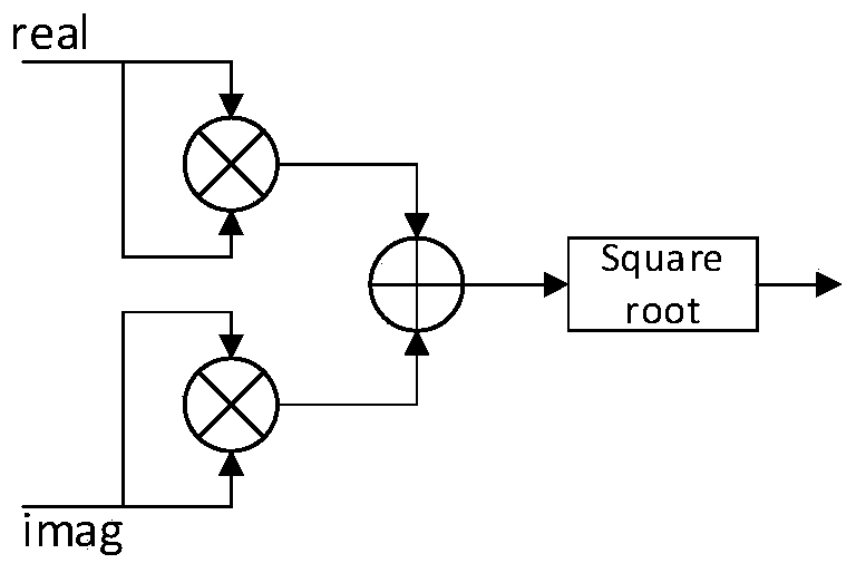
[0068] The moving target to be measured is a vehicle whose maximum size D is equal to 5m, and the radar transmits a chirp signal s(t) to the moving target to be measured, and s(t) is shown in Formula 1, where the pulse width T p Equal to 9us, carrier frequency f c It is equal to 35GHz, the bandwidth B is equal to 8MHz, and the modulation frequency K is equal to 8.89×10 11 , sampling frequency f s It is equal to 10MHz, the number M of pulses repeatedly sent in one coherent processing period is equal to 64, and the pulse repetition period (PRT) T is equal to 60us. Arrange the radar and the moving target to be measured in an unobstructed outdoor environment, the distance between the radar and the moving target to be measured is around 6200m, and the moving target to be measured is within the range of the radar beam with a velocity v equal to 10m / s facing away from the radar sports. Such as figure 1 As shown, the FPGA signal processing part mainly includes a frequency domain p...


PUM


Abstract

The invention belongs to the radio measurement technical field and relates to an FPGA (field-programmable gate array)-based moving target radar cross section measurement method. According to the FPGA(field-programmable gate array)-based moving target radar cross section high-precision measurement realization method, a conventional frequency domain pulse compression hardware structure is improvedin a distance domain, so that a buffer-based frequency domain pulse compression hardware structure can be realized; the theoretical method described in the background art can be realized with only onemultiplying unit adopted; and a new moving target detection and chirp-z transformation combined hardware structure is proposed in the Doppler domain. The method of the invention has the advantages ofclear module structure, high IP multiplexing degree, simple hardware structure, high measurement accuracy, high processing speed, high real-time performance and low power consumption.

Description

technical field [0001] The invention belongs to the technical field of radio measurement, and in particular relates to an FPGA-based method for measuring the radar scattering cross section of a moving target. Background technique [0002] With the development of radar application technology, the application of radar target characteristic measurement becomes more and more important. Radar cross section (RCS), as a physical quantity that quantitatively characterizes the radar scattering characteristics of the target, is an important parameter to measure the radar scattering characteristics of the target. Therefore, the radar cross section measurement of the radar target plays an important role in the field of radio measurement. [0003] In terms of radar cross-section measurement of large targets such as vehicles, Zhulin Zong et al. proposed a method for high-precision radar cross-section measurement in the background of ground clutter in "High Accuracy Measurement of Vehicle ...

Claims


Application Information

Patent Timeline
Patent Type & Authority Patents(China)
IPC IPC(8): G01S7/41
CPCG01S7/41
Inventor 宗竹林马擎堃
Owner UNIV OF ELECTRONICS SCI & TECH OF CHINA
Learn More