Implant conveying system

A delivery system and implant technology, applied in the field of implant delivery system, can solve the problems of inability to adjust the release position, unsatisfactory, the need to adjust the distal position of the outer sheath tube, the position deviation of the lumen stent, etc.

Active Publication Date: 2018-06-22
LIFETECH SCIENTIFIC (SHENZHEN) CO LTD
View PDF9 Cites 16 Cited by
  • Summary
  • Abstract
  • Description
  • Claims
  • Application Information

AI Technical Summary

Problems solved by technology

However, this delivery system still has the following defects: (1) During the delivery of the endoluminal stent, when the outer sheath tube and the sheath core tube pass through the curved part of the human lumen together, at the side where the bending radius of the curved blood vessel is smaller On the side of the sheath core tube and the outer sheath tube, the gap between the sheath core tube and the outer sheath tube decreases; on the side where the bending radius of the curved blood vessel is larger, the gap between the sheath core tube and the outer sheath tube increases, and at this time, the rigid protrusion and the outer sheath tube The distance between the inner walls of the sheath increases, and the rigid protrusions are easier to separate from the lumen stent, and the lumen stent ma

Method used


Image

  • Implant conveying system
  • Implant conveying system
  • Implant conveying system

Examples


Embodiment 1

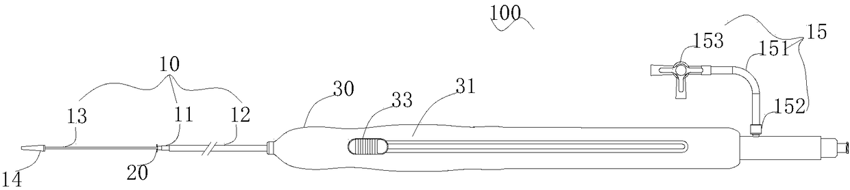
[0050] See figure 1 , the delivery system 100 provided in Embodiment 1 is used to deliver the implant to the lesion in the lumen of the human body. The delivery system 100 includes a tube body 10 , a hooking unit 20 , and a handle including a handle shell 30 and a slider 33 .

[0051] The handle housing 30 includes a first housing 31 and a second housing (not shown in the figure) arranged axially symmetrically. The number of sliders 33 is two. The two sliders 33 are respectively disposed on the first housing 31 and the second housing of the handle housing 30 and are symmetrical to each other.

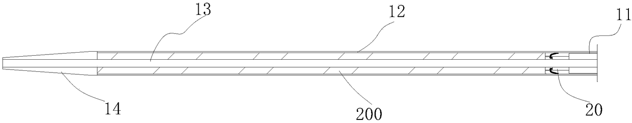
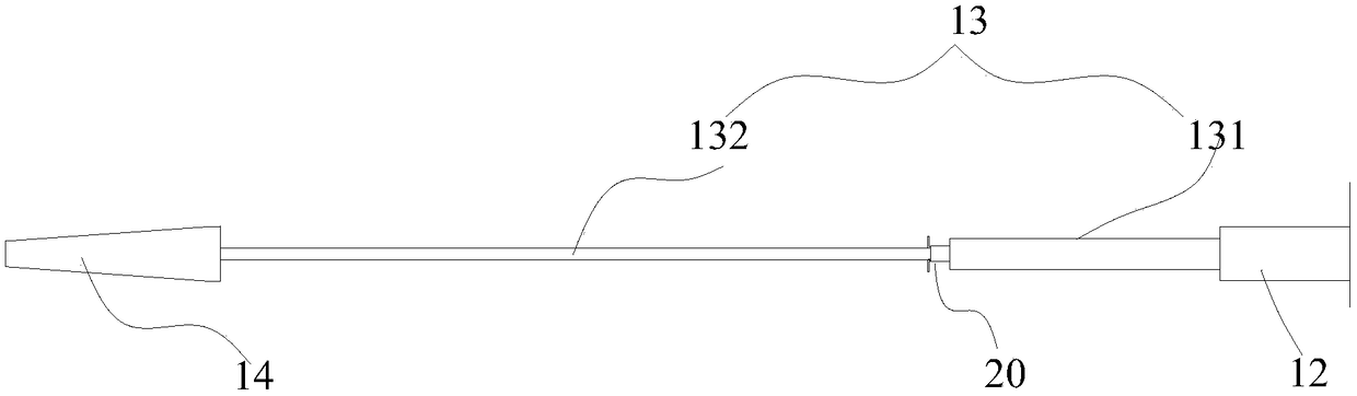
[0052] Please also refer to Figure 2a , in this embodiment, the implant is a lumen stent 200 . The tube body 10 includes a hollow inner sheath tube 11 axially penetrating the handle shell 30, a hollow inner sheath core tube 13 penetrating through the inner sheath tube 11 and having a distal end protruding from the inner sheath tube 11, and is movably sleeved on the inner sheath tub...

Embodiment 2

[0091] The structure of the endoluminal stent delivery system provided in this embodiment is basically the same as that of the endoluminal stent delivery system 100 provided in the first embodiment. The difference is that, in this embodiment, each hooking piece has a U-shaped structure formed by double-strand wires.

[0092] Specifically, see Figure 10a , in this embodiment, the hooking unit includes a hollow tubular tightening member and three hooking members connected to the tightening member. The hooking part has a fixing part connected with the hoop part and a deformation part connected with the fixing part. Each hook is composed of two straight rods and an arc rod connected between the two straight rods.

[0093] Please also see Figure 10b , the radial distance H between the two straight rods ranges from 0.05 to 10 mm. As a result, the reliability of the detachable connection between the lumen support and the hook will not be reduced, nor will it affect the automati...

Embodiment 3

[0102] The structure of the endoluminal stent delivery system provided in this embodiment is basically the same as that of the endoluminal stent delivery system 100 provided in the first embodiment. In this example, see Figure 13a , the delivery system includes a tube body 40 , a handle housing 46 , a slider 47 and a hooking unit 50 . The tube body 40 includes an inner sheath 41 , an outer sheath 42 , an inner sheath core 43 and a tip 44 . The difference is that, in this embodiment, a limiting member 45 is provided on the outer surface of the inner sheath core tube 43 .

[0103] Specifically, please also see Figure 13a and Figure 13b , the limiting member 45 protrudes from the outer surface of the inner sheath core tube 43 in a direction away from the axial direction of the inner sheath core tube 43 . The limiting member 45 is fixed on the outer surface of the inner sheath core tube 43 near the distal end, and is closer to the distal end of the inner sheath core tube 43...


PUM

PropertyMeasurementUnit
Diameteraaaaaaaaaa
Diameteraaaaaaaaaa

Abstract

The invention discloses an implant conveying system, which comprises an inner sheath canal, an inner sheath core pipe which runs through the inner sheath canal and distal end of which extends out of the inner sheath canal, and an outer sheath canal which movably sleeves the exterior of the inner sheath canal and defines a cavity with the inner sheath core pipe, and further comprises at least one hooking unit which is fixed to the outer surface of the inner sheath core pipe, wherein the at least one hooking unit comprises at least two flexible hooking pieces; each hooking piece comprises a fixed part which is connected to the outer surface of the inner sheath core pipe and a deformed part which is connected to the fixed part; and the free end of each deformed part can get bent relative to the fixed part and the free end, when being accommodated within the cavity between the outer sheath canal and the inner sheath core pipe, is matched with the fixed part, so that a hook-shaped object isdefined. According to the implant conveying system provided by the invention, an implant can be fixed to the inner sheath core pipe via the at least one hooking unit, so that the implant is limited from moving. Therefore, in an implant conveying process, the implant is prevented getting deviated from the inner sheath core pipe; and in a release process, early release of the implant can be avoidedwhen the release position of the implant needs to be adjusted.

Description

technical field [0001] The invention relates to an implantable medical device, in particular to a delivery system for the implant. Background technique [0002] For diseases such as vascular stenosis, aneurysm, and vascular dissection, interventional surgery with luminal stents has the advantages of less trauma, faster recovery, fewer complications, and better therapeutic effects. [0003] The metal skeleton structure of the self-expanding stent luminal stent is usually made of nickel-titanium alloy, and after a heat setting process, the luminal stent has the ability to restore its own shape. At present, the tube body of the delivery system of this type of stent generally includes an outer sheath tube and an inner sheath core tube pre-installed in the outer sheath tube. The proximal end of the inner sheath core tube is thicker and the distal end is thinner. The lumen stent is accommodated in the cavity between the outer sheath tube and the distal part of the inner sheath co...

Claims


Application Information

Patent Timeline
IPC IPC(8): A61F2/966A61F2/97
CPCA61F2/966A61F2/97A61F2002/9665A61F2002/9534A61F2002/9511
Inventor 肖本好王琴
Owner LIFETECH SCIENTIFIC (SHENZHEN) CO LTD
Why Eureka
Try Eureka