Thermally activated delayed fluorescent material and application thereof

A technology of heat-activated delayed and fluorescent materials, applied in the direction of luminescent materials, organic chemistry, chemical instruments and methods, etc., can solve the problems of expensive phosphorescent materials and limited application space of phosphorescent materials, and achieve excellent film stability and molecular quality , The effect of device efficiency improvement

Inactive Publication Date: 2018-06-22
VALIANT CO LTD
View PDF1 Cites 3 Cited by
  • Summary
  • Abstract
  • Description
  • Claims
  • Application Information

AI Technical Summary

Problems solved by technology

[0004] The efficiency of phosphorescent devices is higher than that of fluorescent devices. However, phosphorescent devices also have their disadvantages. For example, phosphorescent materials are mainly complexes containing noble metals, especially metal iridium and platinum complexes. Since metal iridium and platinum are expensive, so , the price of phosphorescent materials is extremely expensive, which also limits the application space of phosphorescent materials

Method used


Image

  • Thermally activated delayed fluorescent material and application thereof
  • Thermally activated delayed fluorescent material and application thereof
  • Thermally activated delayed fluorescent material and application thereof

Examples


Embodiment 1

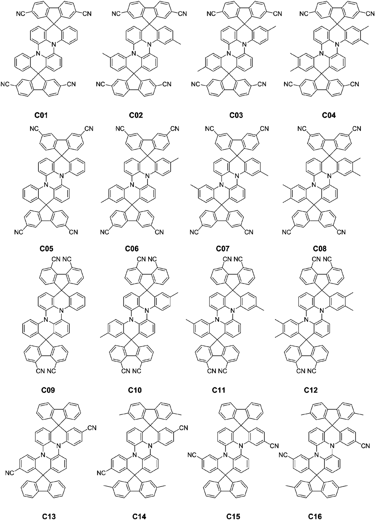
[0035] Embodiment 1: the preparation of compound C01

[0036]

[0037] Preparation of compound S2: In a 500mL three-necked flask, add compound S1 (19.7g, 0.04mol), tetrahydrofuran (210g), cool to -78°C, add dropwise n-butyllithium n-hexane solution (2.2mol / L, 36.5 mL, 0.08mol), the dropwise addition was completed in 1h, and kept at -78°C for 1.5h, and the solid 2,7-dichlorofluorenone (20.0g, 0.08mol) was added to the reaction flask in batches, and reacted at -78°C for 3h. The reaction bottle was moved into an ice-water bath, the temperature was naturally raised to -5°C, 80 g of dilute hydrochloric acid with a mass concentration of 5% was added dropwise to quench the reaction, stirred for 0.5 h, separated, the organic phase was collected, and the solvent was removed under reduced pressure to obtain the crude product of S2 36.2 g, the obtained crude product is no longer refined, and is directly put into the next step reaction.

[0038] Preparation of Compound S3: In a 500mL ...

Embodiment 2

[0040] Embodiment 2: the preparation of compound C03

[0041]

[0042] Using S4 as raw material, referring to the method described in Example 1, compound C03 was prepared to obtain 1.7 g of the target object, high-resolution mass spectrometry, positive ion mode, molecular formula C 56 h 30 N 6 , theoretical value 786.2532, test value 786.2538, elemental analysis (C 56 h 30 N 6 ), theoretical value C: 85.48, H: 3.84, N: 10.68, measured value C: 85.43, H: 3.92, N: 10.65.

Embodiment 3

[0043] Embodiment 3: the preparation of compound C04

[0044]

[0045] Using S5 as raw material, referring to the method described in Example 1, compound C04 was prepared to obtain 1.9 g of the target object, high-resolution mass spectrum, positive ion mode, molecular formula C 58 h 34 N 6 , theoretical value 814.2845, test value 814.2841, elemental analysis (C 58 h 34 N 6 ), theoretical value C: 85.48, H: 4.21, N: 10.31, measured value C: 85.41, H: 4.24, N: 10.35.


PUM

PropertyMeasurementUnit
luminanceaaaaaaaaaa
current efficiencyaaaaaaaaaa

Abstract

The invention discloses a thermally activated delayed fluorescent material and an application thereof, and belongs to the technical field of organic photoelectric materials. The thermally activated delayed fluorescent material has a structure shown in a formula I in the description, wherein R1, R2, R3, R4 and R5 independently represent one of a hydrogen atom, methyl and a cyano group, and at leastone of the R1, the R2, the R3, the R4 and the R5 represents the cyano group. The invention also discloses the application of the above thermally activated delayed fluorescent material. The material provided by the invention has a D-A type molecular structure and a very small deltaEst, can realize thermal activation delay fluorescence luminescence, and can be used as a luminescent layer of a smallmolecule organic electroluminescent device to be applied in the field of organic electroluminescence.

Description

technical field [0001] The invention relates to a thermally activated delayed fluorescent material and its application, belonging to the technical field of organic photoelectric materials. Background technique [0002] Organic electroluminescent diode (OLED) was produced in the 1980s. It has many advantages such as self-illumination, wide viewing angle, fast response speed, wide color gamut, and flexible display. After 30 years of continuous development, the OLED The technology has gradually matured. At present, organic electroluminescent technology has been widely used in many products such as smart phones, flat-panel TVs, and virtual reality. [0003] Organic electroluminescent devices are current-driven light-emitting devices. According to different light-emitting mechanisms, they can be divided into two types: fluorescent devices and phosphorescent devices. When charges are injected into the device from the electrodes, due to the randomness of the electron spin direction...

Claims


Application Information

Patent Timeline
Patent Type & Authority Applications(China)
IPC IPC(8): C07D471/20C09K11/06H01L51/54
CPCC09K11/06C07D471/20C09K2211/1029C09K2211/1044H10K85/6572
Inventor 盛磊张梅高树坤高宪鹏胡葆华杨腾
Owner VALIANT CO LTD
Why Eureka
Try Eureka