Clock circuit with stable duty ratio and low jitter

A clock circuit, low jitter technology, applied in the direction of electrical components, pulse processing, pulse technology, etc., can solve the problems that the duty cycle and accuracy cannot be obtained stably, and cannot meet the requirements of the A/D converter system, so as to improve the convergence The effects of speed, jitter reduction, and high-speed phase detection

Active Publication Date: 2018-06-22
BEIJING MXTRONICS CORP +1
View PDF6 Cites 7 Cited by
  • Summary
  • Abstract
  • Description
  • Claims
  • Application Information

AI Technical Summary

Problems solved by technology

[0004] like figure 1 As shown, ideally, the duty cycle of the clock should be 50% without any jitter. In actual situations, the clock signal source is usually generated and

Method used


Image

  • Clock circuit with stable duty ratio and low jitter
  • Clock circuit with stable duty ratio and low jitter
  • Clock circuit with stable duty ratio and low jitter

Examples


Embodiment Construction

[0033] Exemplary embodiments of the present disclosure will be described in more detail below with reference to the accompanying drawings. Although exemplary embodiments of the present disclosure are shown in the drawings, it should be understood that the present disclosure may be embodied in various forms and should not be limited by the embodiments set forth herein. Rather, these embodiments are provided for more thorough understanding of the present disclosure and to fully convey the scope of the present disclosure to those skilled in the art. It should be noted that, in the case of no conflict, the embodiments of the present invention and the features in the embodiments can be combined with each other. The present invention will be described in detail below with reference to the accompanying drawings and examples.

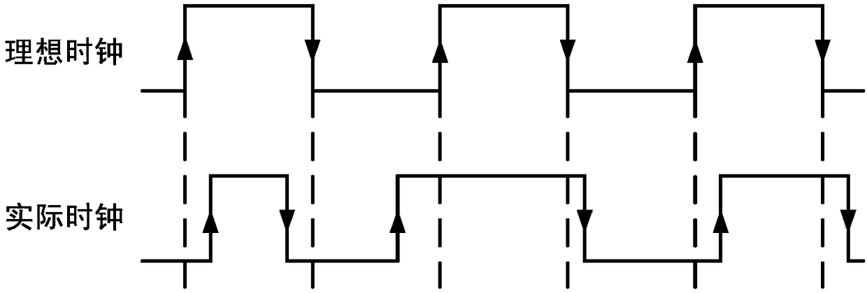
[0034] As the demand for clock speed in communication systems has gradually expanded to the GHz range, certain performances of clocks, such as phase noise and...


PUM


Abstract

The invention discloses a clock circuit with a stable duty ratio and low jitter. The whole clock circuit comprises a clock driving amplifier module, a charge pump module, an output clock falling edgetriggering circuit module, an output clock rising edge triggering circuit module, an output clock waveform stabilization circuit module and a charge pump phase-locked loop module. The clock waveform stabilization circuit generates a complete output clock according to edge control pulses generated by rising edge and falling edge control circuits; the falling edge triggering circuit enables a falling edge of an output clock and a falling edge of an input clock to maintain consistent; the rising edge triggering circuit can take the output clock falling edge as a reference to adjust the output clock rising edge position according to a duty ratio detection result of the input clock, so that the duty ratio of the output clock is finally stabilized to 50%; and the charge pump phase-locked loop receives the output clock of the output clock waveform stabilization circuit module and generates a high-speed low-jitter clock signal. The clock circuit can meet a rigorous requirement for a clock signal in high-frequency application.

Description

technical field [0001] The invention relates to a clock circuit with stable duty ratio and low jitter, which belongs to the field of integrated circuit clock systems and is mainly used to stabilize the duty ratio of high-speed clock signals, reduce clock jitter, and effectively improve the performance of the clock system. Background technique [0002] With the rapid development of communication technology, computer technology, and microelectronics technology, the application of electronic technology has penetrated into every corner of the economic and national defense fields, and various high-performance electronic products continue to emerge. A / D converters will be widely used in data processing and acquisition channels of sensors, and are the core components of electronic systems in these application fields. In a conventional communication system, the receiver generally uses multi-stage down conversion to convert the radio frequency signal to a center frequency low enough ...

Claims


Application Information

Patent Timeline
IPC IPC(8): H03K5/02H03K5/156
CPCH03K5/023H03K5/1565
Inventor 薛培帆张铁良杨松王宗民崔伟赵进才王星树
Owner BEIJING MXTRONICS CORP
Why Eureka
Try Eureka