Transverse flux reluctance type low-speed large-torque direct drive synchronous motor

A transverse magnetic flux, synchronous motor technology, applied in synchronous machines, synchronous motors for single-phase current, magnetic circuit rotating parts, etc. Accurate spatial positioning and phase setting, simplified process flow, high mechanical strength effect

Inactive Publication Date: 2018-07-06
王新
View PDF0 Cites 2 Cited by
  • Summary
  • Abstract
  • Description
  • Claims
  • Application Information

AI Technical Summary

Problems solved by technology

Under air-cooled conditions, the internal temperature rise of the 60-pole radial flux permanent magnet torque motor is as high as 100 °C, which puts forward high requirements for the insulation level of the enameled wire and the working temperature level of the NdFeB permanent magnet, resulting in Increased motor cost
In the design of multi-pole logarithmic motors, the fundamental defect of the electromagnetic structure of conventional radial flux motors is that radial flux motors can only be improved by increasing the number of slo...

Method used


Image

  • Transverse flux reluctance type low-speed large-torque direct drive synchronous motor
  • Transverse flux reluctance type low-speed large-torque direct drive synchronous motor
  • Transverse flux reluctance type low-speed large-torque direct drive synchronous motor

Examples


Embodiment Construction

[0052] In the transverse flux reluctance type low-speed high-torque direct drive synchronous motor of the present invention, the main purpose of mechanical manufacturing and structure is to wind each phase winding on the stator base, and install the discrete phase stators and rotor cores on the stator and on the rotor base. Hereinafter, specific embodiments of the present invention will be described in detail in conjunction with the accompanying drawings.

[0053] The primary task of implementing the present invention is to manufacture the stator iron core and the rotor iron core, and the manufacturing steps are as follows:

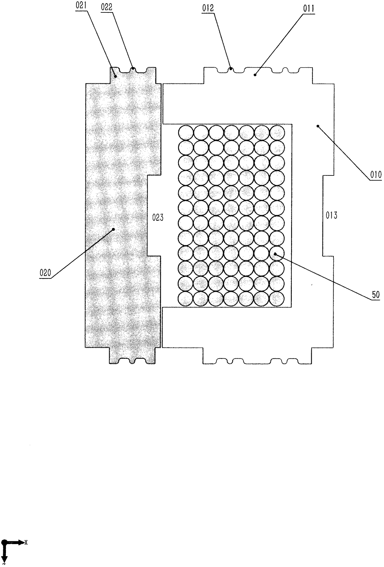
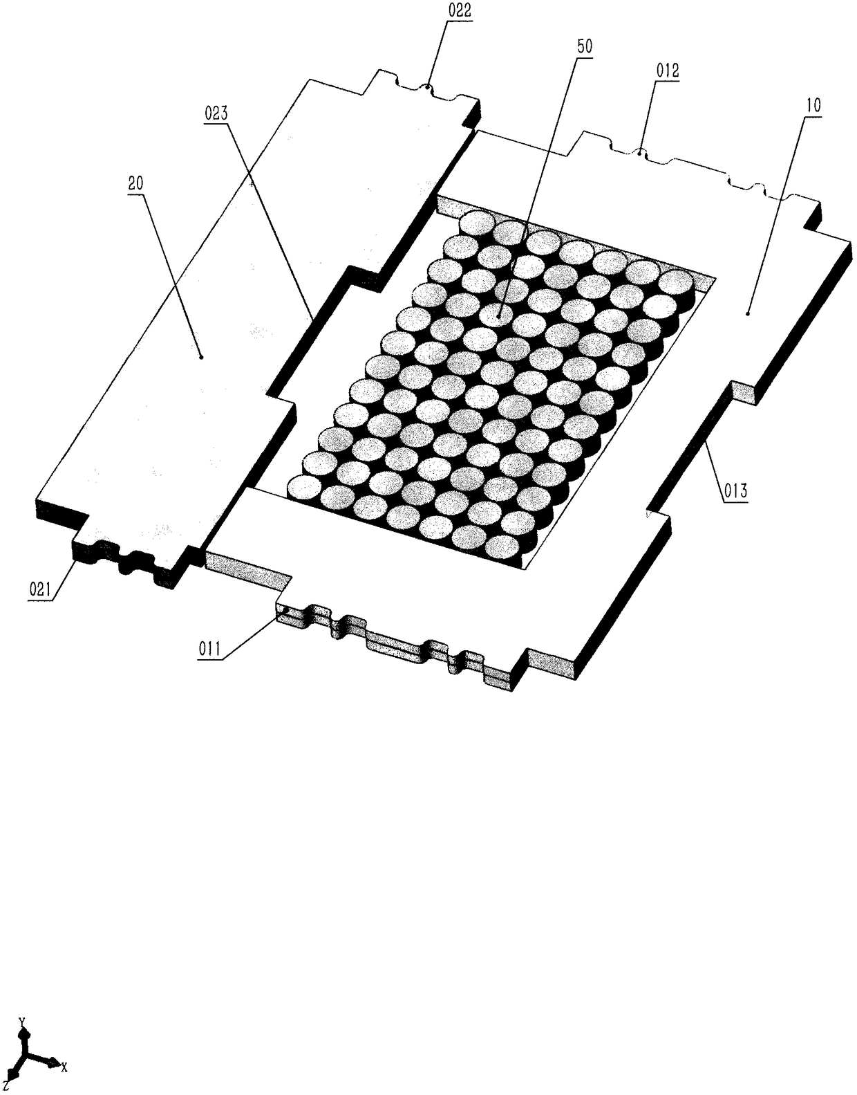
[0054] (1) Stator and rotor core punching sheets are made by punching silicon steel sheets. For the pattern of stator core punch 010 and rotor core punch 020, see figure 1 , the basic figure of the stator core punching sheet 010 is "U" shape, there are rectangular protrusions 011 on both sides of the stator core punching sheet 010, and its outer edge is...


PUM


Abstract

The force density of the transverse flux reluctance type low-speed large-torque direct drive synchronous motor is 3-5 times that of the existing radial flux motor. The motor consists of a stator and arotor iron core, a stator and a rotor base body, a phase winding and the like. The stator and the rotor iron core are manufactured by adopting silicon steel sheet punching, rotor iron core punching,cambered surface lamination and argon arc welding to form a stator and a rotor iron core. The stator base body and the rotor base body are axially divided into an m-phase segment, and the pole logarithm of each phase segment is p. The m-phase annular winding is directly wound on the channel of each phase of the stator base, and 2p stator cores are installed in each window segment, distributed circumferentially around the motor axis; 2p rotors are installed in the window hole of each phase of the rotor base, distributed in a circumferential array around the axis of the motor. Each phase rotor core is radially aligned, and each phase stator core is radially offset from each other by a 1/m pole pitch angle. Under the same rated power, the invention realizes the multi-pole logarithmic design of the motor by reducing the thickness of stator and rotor core and increasing the number of stator cores.

Description

technical field [0001] The invention belongs to the field of motor manufacturing, in particular to a transverse flux reluctance type low-speed high-torque direct drive synchronous motor. Background technique [0002] The low-speed high-torque direct drive motor eliminates the heavy reduction mechanism and avoids various adverse effects such as complex structure, large moment of inertia, low efficiency, lubricating oil leakage, wear and tear, and frequent maintenance. Low-speed high-torque direct drive motors are widely used in metal wire drawing machines, elevator traction devices, hoisting machinery, tower pumping units, mine explosion-proof motors, air-cooled island fans, belt transportation, wind power generators and other fields. [0003] In order to realize the low speed, high torque density, and direct drive of the motor below 100r / min, the design and manufacture of the number of pole pairs ≥ 30 must be realized. Based on the fundamental difference in the electromagne...

Claims


Application Information

Patent Timeline
IPC IPC(8): H02K19/10H02K1/16H02K1/22H02K15/02
CPCH02K19/103H02K1/165H02K1/22H02K15/02H02K15/026H02K2213/03
Inventor 王新
Owner 王新
Why Eureka
Try Eureka