Flue gas denitration device and denitration method
A flue gas and denitrification technology, which is applied in the flue gas denitrification device and its denitrification field, can solve the problems that it is difficult to reach the catalyst activation temperature of the SCR method, the sintering flue gas is difficult to SCR technology, and the flue gas contains corrosive gases, etc., and achieves good economy. performance, increase life, and reduce investment costs
- Summary
- Abstract
- Description
- Claims
- Application Information
AI Technical Summary
Problems solved by technology
Method used
Image

Examples
Embodiment 1
[0056] A flue gas denitrification method, the specific steps are as follows:
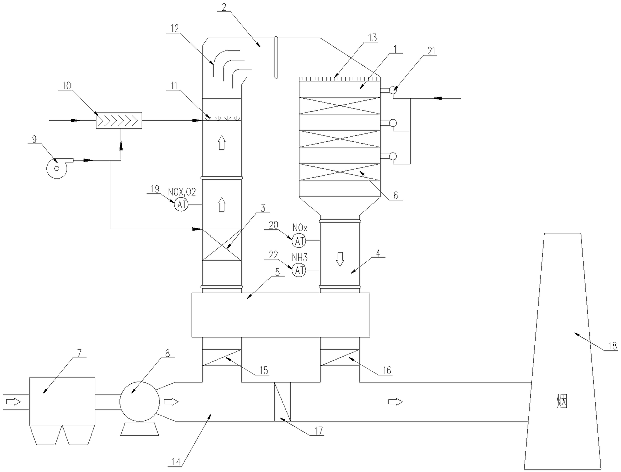
[0057] 1) Flue gas electrostatic dust removal: the flue gas before denitrification is passed into the electrostatic precipitator 7 of the sintering machine for electrostatic dust removal, and the flue gas after dust removal is introduced into the flue 14 through the induced draft fan 8;
[0058] 2) Flue gas heat exchange and heating: the flue gas in the flue 14 enters the air heat exchanger 5 through the intake valve 15 for temperature rise and heat exchange, and the flue gas after heat exchange enters the flue heater 3 for heating. The heated flue gas flows in the intake pipe and passes through the ammonia injection grid 11; the air heat exchanger 5 exchanges heat between the flue gas after denitration and the flue gas before denitration, and exchanges the temperature of the flue gas before denitration When it is heated to about 200°C, the flue heater 3 uses coke oven gas as fuel to heat the flue g...
Embodiment 2
[0064] A flue gas denitrification method, the specific steps are as follows:
[0065] 1) Flue gas electrostatic dust removal: the flue gas before denitrification is passed into the electrostatic precipitator 7 of the sintering machine for electrostatic dust removal, and the flue gas after dust removal is introduced into the flue 14 through the induced draft fan 8;
[0066] 2) Flue gas heat exchange and heating: the flue gas in the flue 14 enters the air heat exchanger 5 through the intake valve 15 for temperature rise and heat exchange, and the flue gas after heat exchange enters the flue heater 3 for heating. The heated flue gas flows in the intake pipe and passes through the ammonia injection grid 11; the air heat exchanger 5 exchanges heat between the flue gas after denitration and the flue gas before denitration, and exchanges the temperature of the flue gas before denitration When it is heated to 250°C, the flue heater 3 uses coke oven gas as fuel to heat the flue gas to ...
Embodiment 3
[0072] A flue gas denitrification method, the specific steps are as follows:
[0073] 1) Flue gas electrostatic dust removal: the flue gas before denitrification is passed into the electrostatic precipitator 7 of the sintering machine for electrostatic dust removal, and the flue gas after dust removal is introduced into the flue 14 through the induced draft fan 8;
[0074] 2) Flue gas heat exchange and heating: the flue gas in the flue 14 enters the air heat exchanger 5 through the intake valve 15 for temperature rise and heat exchange, and the flue gas after heat exchange enters the flue heater 3 for heating. The heated flue gas flows in the intake pipe and passes through the ammonia injection grid 11; the air heat exchanger 5 exchanges heat between the flue gas after denitration and the flue gas before denitration, and exchanges the temperature of the flue gas before denitration When it is heated to 225°C, the flue heater 3 uses coke oven gas as fuel to heat the flue gas to ...
PUM
 Abstract
Description
Claims
Application Information
 - R&D
- Intellectual Property
- Life Sciences
- Materials
- Tech Scout
- Unparalleled Data Quality
- Higher Quality Content
- 60% Fewer Hallucinations
Browse by: Latest US Patents, China's latest patents, Technical Efficacy Thesaurus, Application Domain, Technology Topic, Popular Technical Reports.
© 2025 PatSnap. All rights reserved.Legal|Privacy policy|Modern Slavery Act Transparency Statement|Sitemap|About US| Contact US: help@patsnap.com