High-hardness wear-resisting polishing head material and efficient polishing device
A grinding head, high-hardness technology, applied in abrasives, grinding machines, grinding machine parts, etc., can solve the problems of poor grinding quality, strong fatigue, and low grinding efficiency, and achieve high wear resistance, high hardness, and difficult worn effect
- Summary
- Abstract
- Description
- Claims
- Application Information
AI Technical Summary
Problems solved by technology
Method used
Image
Examples
Embodiment 1
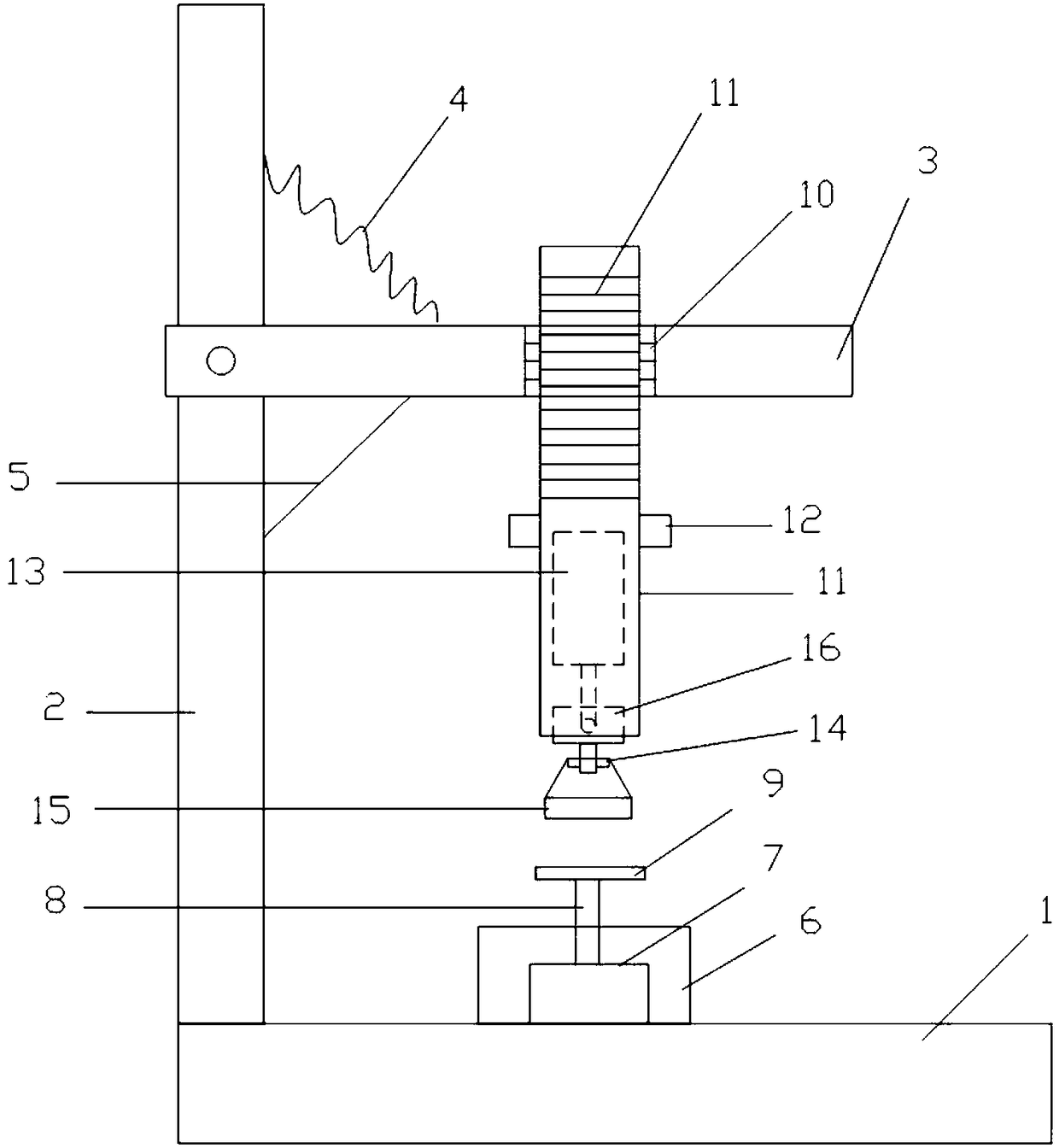
[0022] Such as figure 1 As shown, a high-efficiency grinding device includes a workbench 1, a frame 2 installed above the workbench 1, and a crossbar 3 installed on the frame 2, between the frame 2 and the crossbar 3 Connected with spring 4 and stay cord 5, described spring 4 is positioned at the top of described stay cord 5, and described workbench 1 is provided with polishing seat 6, and described polishing seat 6 is provided with lifting motor 7, and described lifting motor 7 above is connected with a lifting rod 8, and the lifting rod 8 is connected with a lifting platform 9, and the cross bar 3 is provided with an internally threaded hole 10, and a sleeve 11 is screwed into the internally threaded hole 10, and the sleeve 11 A limit block 12 is fixed outside the cylinder 11, the sleeve 11 is hollowed out, a micro motor 13 is provided inside the sleeve 11, an adapter block 14 is provided at the outlet of the sleeve 11, and the micro motor 13 The drive shaft of the adapter ...
Embodiment 2
[0024] Such as figure 1 As shown, a high-efficiency grinding device includes a workbench 1, a frame 2 installed above the workbench 1, and a crossbar 3 installed on the frame 2, between the frame 2 and the crossbar 3 Connected with spring 4 and stay cord 5, described spring 4 is positioned at the top of described stay cord 5, and described workbench 1 is provided with polishing seat 6, and described polishing seat 6 is provided with lifting motor 7, and described lifting motor 7 above is connected with a lifting rod 8, and the lifting rod 8 is connected with a lifting platform 9, and the cross bar 3 is provided with an internally threaded hole 10, and a sleeve 11 is screwed into the internally threaded hole 10, and the sleeve 11 A limit block 12 is fixed outside the cylinder 11, the sleeve 11 is hollowed out, a micro motor 13 is provided inside the sleeve 11, an adapter block 14 is provided at the outlet of the sleeve 11, and the micro motor 13 The drive shaft of the adapter ...
Embodiment 3
[0026] Such as figure 1 As shown, a high-efficiency grinding device includes a workbench 1, a frame 2 installed above the workbench 1, and a crossbar 3 installed on the frame 2, between the frame 2 and the crossbar 3 Connected with spring 4 and stay cord 5, described spring 4 is positioned at the top of described stay cord 5, and described workbench 1 is provided with polishing seat 6, and described polishing seat 6 is provided with lifting motor 7, and described lifting motor 7 above is connected with a lifting rod 8, and the lifting rod 8 is connected with a lifting platform 9, and the cross bar 3 is provided with an internally threaded hole 10, and a sleeve 11 is screwed into the internally threaded hole 10, and the sleeve 11 A limit block 12 is fixed outside the cylinder 11, the sleeve 11 is hollowed out, a micro motor 13 is provided inside the sleeve 11, an adapter block 14 is provided at the outlet of the sleeve 11, and the micro motor 13 The drive shaft of the adapter ...
PUM
 Abstract
Description
Claims
Application Information
 - R&D
- Intellectual Property
- Life Sciences
- Materials
- Tech Scout
- Unparalleled Data Quality
- Higher Quality Content
- 60% Fewer Hallucinations
Browse by: Latest US Patents, China's latest patents, Technical Efficacy Thesaurus, Application Domain, Technology Topic, Popular Technical Reports.
© 2025 PatSnap. All rights reserved.Legal|Privacy policy|Modern Slavery Act Transparency Statement|Sitemap|About US| Contact US: help@patsnap.com

