Multi-effect sludge drying chamber

A sludge and drying technology, applied in the direction of dehydration/drying/concentrated sludge treatment, etc., can solve the problems of low energy utilization rate, achieve good technical effects, improve utilization rate, and avoid secondary pollution

Inactive Publication Date: 2018-07-20
SHANDONG BAOTA NEW ENERGY CO LTD
View PDF0 Cites 0 Cited by
  • Summary
  • Abstract
  • Description
  • Claims
  • Application Information

AI Technical Summary

Problems solved by technology

[0004] The present invention aims at the technical defects of the prior art, and provides a sludge multi-effect d...

Method used


Image

  • Multi-effect sludge drying chamber

Examples


Embodiment 1

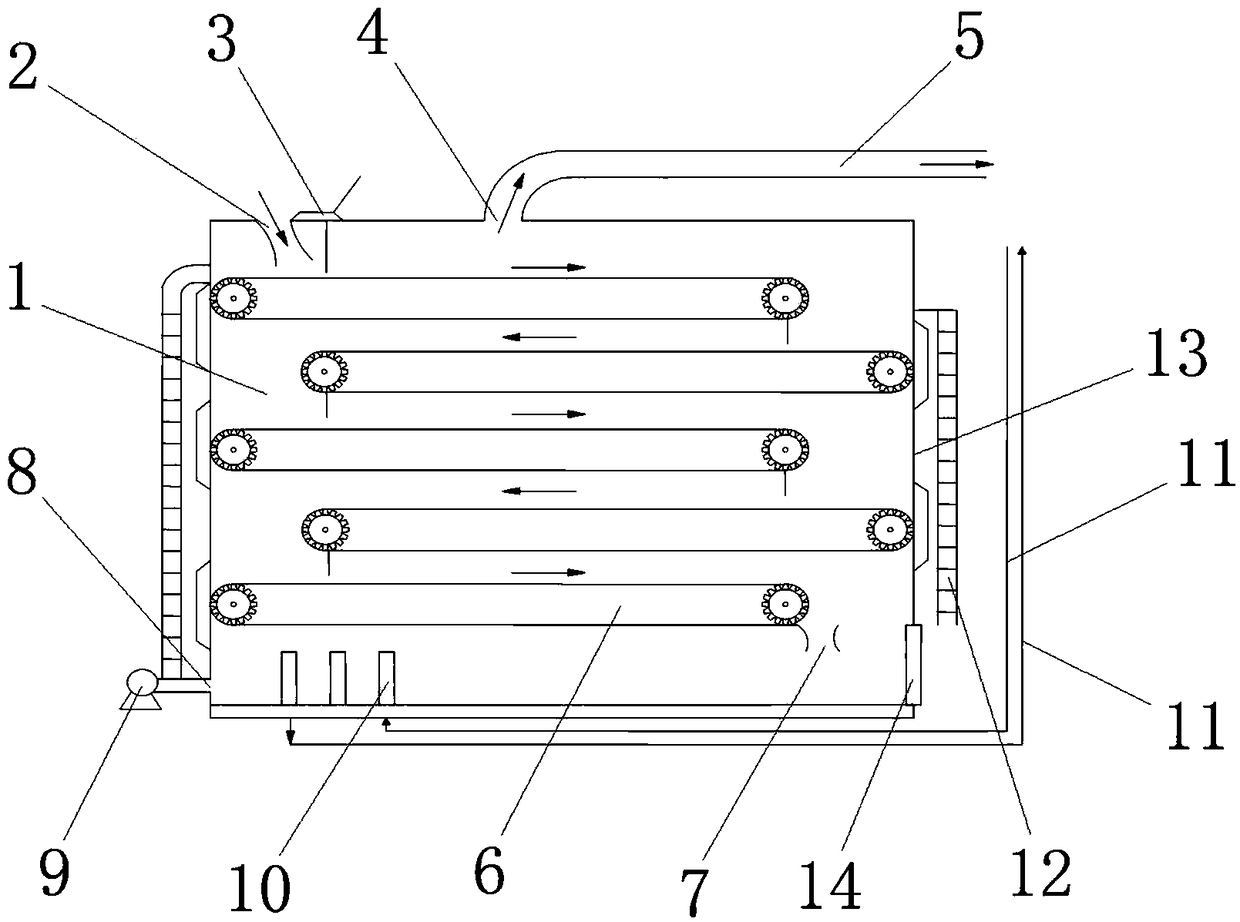
[0023] Multi-effect drying room for sludge, such as figure 1 As shown, it includes bin body 1, feeding port 2, cover plate 3, exhaust port 4, exhaust gas pipeline 5, conveyor belt 6, discharge port 7, air inlet 8, fan 9, heat exchanger 10, condensate pipeline 11 , Observation ladder 12, inspection port 13, bin door 14, wherein the feeding port 2 is located at the top of the bin body 1, the feeding port 2 is connected with a cover 3, and the top of the bin body 1 is also provided with an exhaust port 4 An exhaust gas pipeline 5 is connected to the exhaust port 4, a number of conveyor belts 6 staggered from top to bottom are arranged inside the bin body 1, and the discharge port 7 is located at the edge of the lowermost conveyor belt 6; One side of the lower end of the body 1 has an air inlet 8, and the other side of the lower end of the warehouse body 1 is connected with a warehouse door 14. The air inlet 8 is provided with a fan 9 which is located outside the warehouse body 1. ...

Embodiment 2

[0027] Multi-effect sludge drying room, including bin body 1, feeding port 2, cover plate 3, exhaust port 4, exhaust gas pipeline 5, conveyor belt 6, discharge port 7, air inlet 8, fan 9, heat exchanger 10 , Condensate pipeline 11, observation ladder 12, inspection port 13, warehouse door 14, wherein the feeding port 2 is located at the top of the silo body 1, the feeding port 2 is connected with a cover 3, and the top of the silo body 1 is also provided There is an exhaust port 4, and an exhaust gas pipeline 5 is connected to the exhaust port 4. A number of conveyor belts 6 arranged alternately are arranged from top to bottom inside the bin body 1, and the discharge port 7 is located at the lowermost conveyor belt 6 One side of the lower end of the warehouse body 1 has an air inlet 8, the other side of the lower end of the warehouse body 1 is connected to a warehouse door 14, the air inlet 8 is provided with a fan 9, the fan 9 is located outside the warehouse body 1 , The blow...


PUM


Abstract

The invention provides a multi-effect sludge drying chamber, and belongs to the technical field of sludge drying. According to the technical scheme, sludge moves downwards along with a conveyor belt in sequence in vertical space and keeps in contact with countercurrent hot air constantly in the process, and accordingly the drying area of the sludge and the use ratio of the space are effectively increased. Meanwhile, exhaust gas waste heat, condensed water heat release and solar radiant heat are combined, the energy consumption level is remarkably reduced. Besides, sludge conveying and air flowwaftage are both completed in a mechanical way, and thus the automation degree is high, and human resources are saved. On that basis, if a detection unit and an electronic control unit are further introduced, automatic control over the device can be implemented. Exhaust gases after treatment are collected collectively, and secondary pollution to the environment is avoided. The multi-effect sludgedrying chamber achieves a good technical effect through novel technical improvement and is reasonable in structure, the scheme adapts to local conditions, and the drying chamber has a wide application prospect.

Description

Technical field [0001] The invention relates to the technical field of sludge drying, and further relates to a sludge drying treatment equipment, in particular to a sludge multi-effect drying room. Background technique [0002] Sludge is the product of sewage treatment, and it is an extremely complex heterogeneous body composed of organic debris, bacterial cells, inorganic particles, and colloids. Its water content is extremely high. Calculated with a water content of 97%, its volume accounts for 0.3% to 0.5% of the treated sewage. If advanced treatment, the mud yield will increase by 50% to 100%. It is large in size, difficult to store, and has a big peculiar smell. , Serious pollution and other problems. In this case, if it is not dried and reduced, the subsequent transportation and processing links will be difficult to carry out. [0003] In the prior art, the drying methods of sludge mainly include: natural drying, thermal power evaporation, large-area board room drying or dr...

Claims


Application Information

Patent Timeline
IPC IPC(8): C02F11/12
CPCC02F11/12
Inventor 刘波李伟沈辉李振堂于彪
Owner SHANDONG BAOTA NEW ENERGY CO LTD
Why Eureka
Try Eureka