
High-utilization-ratio and high-uniformity LED illumination system used in direct-write photoetching machine

A technology of LED lighting and utilization rate, applied in the field of LED lighting system, can solve problems such as low light source utilization rate, difficult debugging and maintenance, complex structure, etc., achieve good light uniformity, reduce complexity, design difficulty, and high luminous efficiency Effect

Pending Publication Date: 2018-07-20
HEFEI CHIP FOUND MICROELECTRONICS EQUIP CO LTD
View PDF3 Cites 0 Cited by
  • Summary
  • Abstract
  • Description
  • Claims
  • Application Information

AI Technical Summary

Problems solved by technology

[0007] In view of the problems of low light source utilization rate, complex structure, difficult debugging and maintenance, and high cost in the existing direct-writing lithography machine lighting system, the purpose of the present invention is to provide an LED lighting system with high utilization rate and high uniformity in the direct-writing lithography machine , has the characteristics of high light source utilization rate, good illumination uniformity, simple structure, easy assembly, low precision requirements, low cost and high yield rate

Method used


Image

  • High-utilization-ratio and high-uniformity LED illumination system used in direct-write photoetching machine
  • High-utilization-ratio and high-uniformity LED illumination system used in direct-write photoetching machine
  • High-utilization-ratio and high-uniformity LED illumination system used in direct-write photoetching machine

Examples


Embodiment Construction

[0026] The present invention will be further described below with reference to the drawings and specific embodiments.

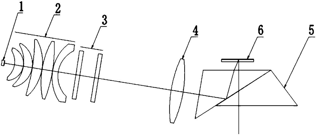
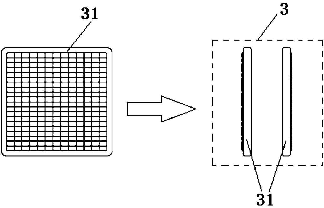
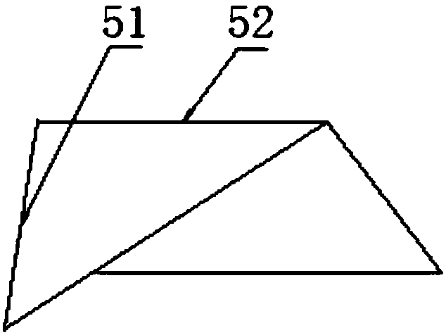
[0027] Such as figure 1 As shown, an LED lighting system with high utilization and high uniformity in a direct writing lithography machine includes an LED light source 1, a collimator lens group 2, a homogenizing lens group 3, a condenser lens 4, and a turning prism 5. The centers of the LED light source 1, the collimator lens group 2, the homogenizing lens group 3 and the condenser lens 4 are all located on the same axis, and the turning prism 5 is located under the DMD digital mask 6. The numerical aperture corresponding to the divergence angle of the emitted light of the LED light source 1 is NA 0.85, and this super large numerical aperture is adopted to achieve high utilization of the illumination system. The LED light source 1 can be a single LED lamp bead or an array of multiple LED lamp beads. Such as figure 2 As shown, the homogenization lens group 3 i...


PUM


Abstract

The invention provides a high-utilization-ratio and high-uniformity LED illumination system used in a direct-write photoetching machine. The LED illumination system comprises an LED light source, andalso comprises a collimating mirror group, a light uniformizing mirror group, a condensing lens and a turning prism; the centers of the LED light source, the collimating mirror group, the light uniformizing mirror group and the condensing lens are all positioned on the same axis; the turning prism is positioned below a DMD digital mask; the numerical aperture corresponding to the emergent light divergence angle of the LED light source is NA0.85; the light uniformizing mirror group is formed by a pair of microlens arrays combined symmetrically; the incident plane of the turning prism is perpendicular to the axis; and the emergent plane of the turning prism is parallel to the DMD digital mask. The high-utilization-ratio and high-uniformity LED illumination system has the characteristics of high light source utilization rate, high luminance uniformity, simple structure, easy assembling, low precision requirement, low cost and high yield.

Description

Technical field [0001] The invention relates to the technical field of optical system design of a direct writing lithography machine, in particular to an LED lighting system with high utilization and high uniformity in a direct writing lithography machine. Background technique [0002] The lithography machine is a device used to print the pattern on the surface of the substrate. The direct write lithography machine is different from the traditional lithography machine. It uses an independently addressable and controllable pixel array, that is, a DMD digital mask. The magnification is projected onto the photosensitive element substrate to produce a feature pattern, thereby eliminating the need for manufacturing and using masks in the traditional photolithography process, reducing time and cost. [0003] The illumination system is one of the important components of the optical system of the direct-write lithography machine. Its light source type and system structure not only affect ...

Claims


Application Information

Patent Timeline
Patent Type & Authority Applications(China)
IPC IPC(8): G03F7/20
CPCG03F7/2057G03F7/70075G03F7/70141G03F7/7015
Inventor 杨宇航吴琼何少锋李永强项宗齐
Owner HEFEI CHIP FOUND MICROELECTRONICS EQUIP CO LTD
Learn More