Necking type steel bar connecting sleeve, connecting structure thereof and installing method of connecting structure

A technology of steel connection sleeve and installation method, which is applied in the direction of structural elements, building components, building structures, etc., can solve the problems of difficult quality control, hidden dangers of building safety, and high connection strength, so as to improve the accuracy of the assembly position and improve the corrosion resistance. performance, the effect of improving connection strength

Pending Publication Date: 2018-07-24
李藏柱
View PDF8 Cites 21 Cited by
  • Summary
  • Abstract
  • Description
  • Claims
  • Application Information

AI Technical Summary

Problems solved by technology

[0004] Advantages: Simple installation and operation; Disadvantages: Due to the welding process, the performance of the connected steel plate is brittle, resulting in poor toughness / easy cracking / low connection strength of the steel plate, poor structural connection integrity / air tightness / seismic resistance, poor corrosion resistance / durability; now Belongs to obsolete technology, the market application range is small
The advantage is that the connection strength is higher than the welding strength, and the disadvantages are: high cost, poor structural connection integrity / air tightness / seismic resistance, poor corrosion resistance / durability; small market application range
[0009] Disadvantages: In practical application, the following problems need to be improved in the steel sleeve grouting connection technology: 1. The construction operation is difficult due to factors such as steel bar deformation, displacement, and small installation gap; 2. The problem of grout leakage is easy to occur and cannot be inspected; 3. .The operation process is complex, requiring special equipment, tools, materials, and personnel; 4. High cost and difficult to control the quality; 4. There are many factors affecting the quality of grouting materials (materials, water-cement ratio, mixing, grouting, grout leakage, personnel operation , application time, etc.), quality control is difficult; 5. Since the steel sleeve grouting connection technology is to bond the steel bar to the sleeve through the grouting material, the steel bar connection is realized by using the friction principle and function
Therefore, as the connection medium, the grouting material plays a decisive role in the quality of the connection. The grout must be full, without leakage, and without shrinkage. However, in the actual application process, especially the connection of vertical components (which is prone to leakage and cannot be inspected) is very difficult. Guarantee the quality of the connection, poor quality controllability; the quality of the connection directly affects the connection strength of the steel bar, forming an invalid connection (reinforcement core pulling phenomenon), causing hidden dangers to building safety
[0010] In addition, even if there is no problem with the quality of the steel sleeve grouting connection, there is still an unsolvable technical problem in the structural connection: the integrity of the structural connection of the vertical concrete prefabricated components, that is, the bottom of the prefabricated component and the cast-in-place layer of the laminated slab The problem of horizontal joints between
Because the strength of the mortar (adhesive / leveling layer) at the bottom of the component is lower than the strength of the concrete of the prefabricated component when the vertical prefabricated component is installed, the stress point is weak, which affects the poor integrity of the concrete structure and low seismic resistance.

Method used


Image

  • Necking type steel bar connecting sleeve, connecting structure thereof and installing method of connecting structure
  • Necking type steel bar connecting sleeve, connecting structure thereof and installing method of connecting structure
  • Necking type steel bar connecting sleeve, connecting structure thereof and installing method of connecting structure

Examples


Embodiment 1

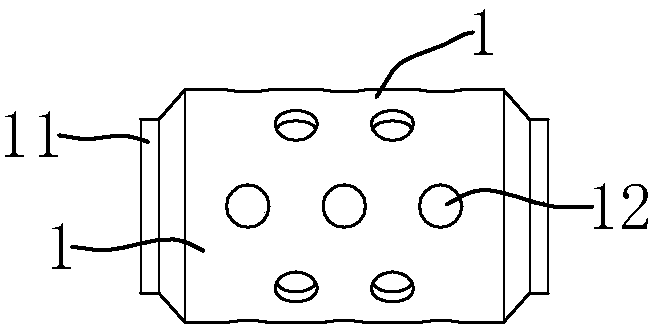
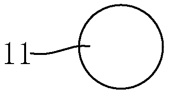
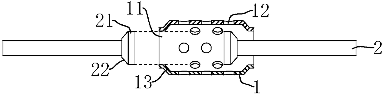
[0103] Necked steel bar connection sleeve and its connection structure, such as figure 1 As shown, the necking-type steel bar connecting sleeve includes a cylinder 1 and a necking 11 integrally connected to both ends of the cylinder 1. Several evenly distributed grouting holes 12 are opened on the cylinder 1 to facilitate the flow of cement slurry into the cylinder 1. inside; combine figure 2 , the necking 11 is a round mouth, the inner wall of the necking 11 is conical, and the larger end of the conical surface faces the inside of the cylinder 1; combined image 3 , the connection structure of the necked steel bar connecting sleeve is composed of the connecting steel bar 2 and the cylinder body 1. One end of the connecting steel bar 2 is embedded and fixed inside the prefabricated slab 3, and the other end is exposed outside the prefabricated slab 3 and far away from the prefabricated slab 3. One end is integrally connected with an expanding head 21, the radial dimension o...

Embodiment 2

[0109] The necking-type steel bar connection sleeve and its connection structure are different from Embodiment 1 in that, as Figure 5 As shown, the constriction 11 is a flat mouth, such as elongated or oval; the enlarged head 21 is a flat head. Taking the ellipse as an example for illustration, the length of the major axis of the ellipse of the expanding head 21 is greater than the length of the minor axis of the ellipse of the constriction 11. Make the elliptical major axis of the enlarging head 21 and the elliptical major axis of the constriction 11 stagger, preferably, the elliptic major axis of the enlarging head 21 is aligned with the elliptical minor axis of the constriction 11, which can limit the enlarging head 21 from the constriction. Port 11 is out of barrel 1 .

[0110] Preferably, as Figure 6 and Figure 7 As shown, a plurality of connecting steel bars 2 can be inserted at both ends of the cylinder body 1, and there can be two. The expanding head 21 is inser...

Embodiment 3

[0112] The necking-type steel bar connection sleeve and its connection structure are different from Embodiment 1 in that, as Figure 8 As shown, anti-skid lines 14 are provided on the inner wall of the cylinder 1 , the anti-slip lines 14 are in the shape of annular grooves, and a plurality of anti-slip lines 14 are evenly distributed along the central axis of the cylinder 1 . After the cement slurry is solidified inside the cylinder 1 to form concrete, the concrete can be embedded in the grooves of the anti-skid lines 14 to improve the connection strength between the inner wall of the cylinder 1 and the inner concrete, and avoid relative sliding between the concrete and the inner wall of the cylinder 1 .


PUM


Abstract

The invention discloses a necking type steel bar connecting sleeve, a connecting structure thereof and an installing method of the connecting structure. The necking type steel bar connecting sleeve comprises a sleeve body and a connecting steel bar, wherein grouting holes are formed in the sleeve body; two ends of the necking type steel bar connecting sleeve are fixedly connected with necking openings; the end part of the connecting steel bar is fixedly connected with an enlarging head; the enlarging head can be inserted to the inner part of the sleeve body through the necking openings; two ends of the sleeve body are respectively arranged on the connecting steel bar in a sleeving way; concrete can be formed through solidification after concreting; the necking openings can limit the concrete and the enlarging head to move towards direction of pulling out sleeve; the enlarging head can be fixed to the inner part of the sleeve body by the concrete; the connecting steel bar and the sleevebody can be fixedly connected; one end, which is far away from the sleeve body, of the connecting steel bar is fixed to the inner part of a prefabricated slab required to be connected in a pre-embedded way; two prefabricated slabs can be connected; installation of the sleeve body is simple and convenient, the cost is low, and the connecting strength is high.

Description

technical field [0001] The invention relates to a steel bar connection structure, in particular to a necked sleeve connection structure. Background technique [0002] At present, the connection methods of prefabricated components in prefabricated concrete structure buildings, especially the vertical reinforcement connection methods of vertical components (prefabricated wall panels / columns) mainly include: 1) welding connection of embedded parts, 2) bolt connection of embedded parts , 3) There are three connection methods for steel sleeve grouting connection. [0003] 1) The welding connection of embedded parts is that the connecting steel plate is preset at the connecting part of the component, and after the prefabricated component is installed, the adjacent embedded steel plate between the components is welded and connected into one. [0004] Advantages: Simple installation and operation; Disadvantages: Due to the welding process, the performance of the connected steel pla...

Claims


Application Information

Patent Timeline
Patent Type & Authority Applications(China)
IPC IPC(8): E04C5/16
CPCE04C5/165
Inventor 李藏柱
Owner 李藏柱
Why Eureka
Try Eureka