
Wave plate design and error correction method in contrast ratio adjustable point diffraction interference system

A point diffraction interference and error correction technology, applied in the optical field, can solve the problems of reducing detection efficiency, large wavefront distortion aberration and polarization aberration, and increasing the complexity of installation and adjustment, so as to achieve simple system adjustment and reduce wavefront distortion. The effect of aberration

Active Publication Date: 2018-07-27
ZHEJIANG UNIV
View PDF5 Cites 2 Cited by
  • Summary
  • Abstract
  • Description
  • Claims
  • Application Information

AI Technical Summary

Problems solved by technology

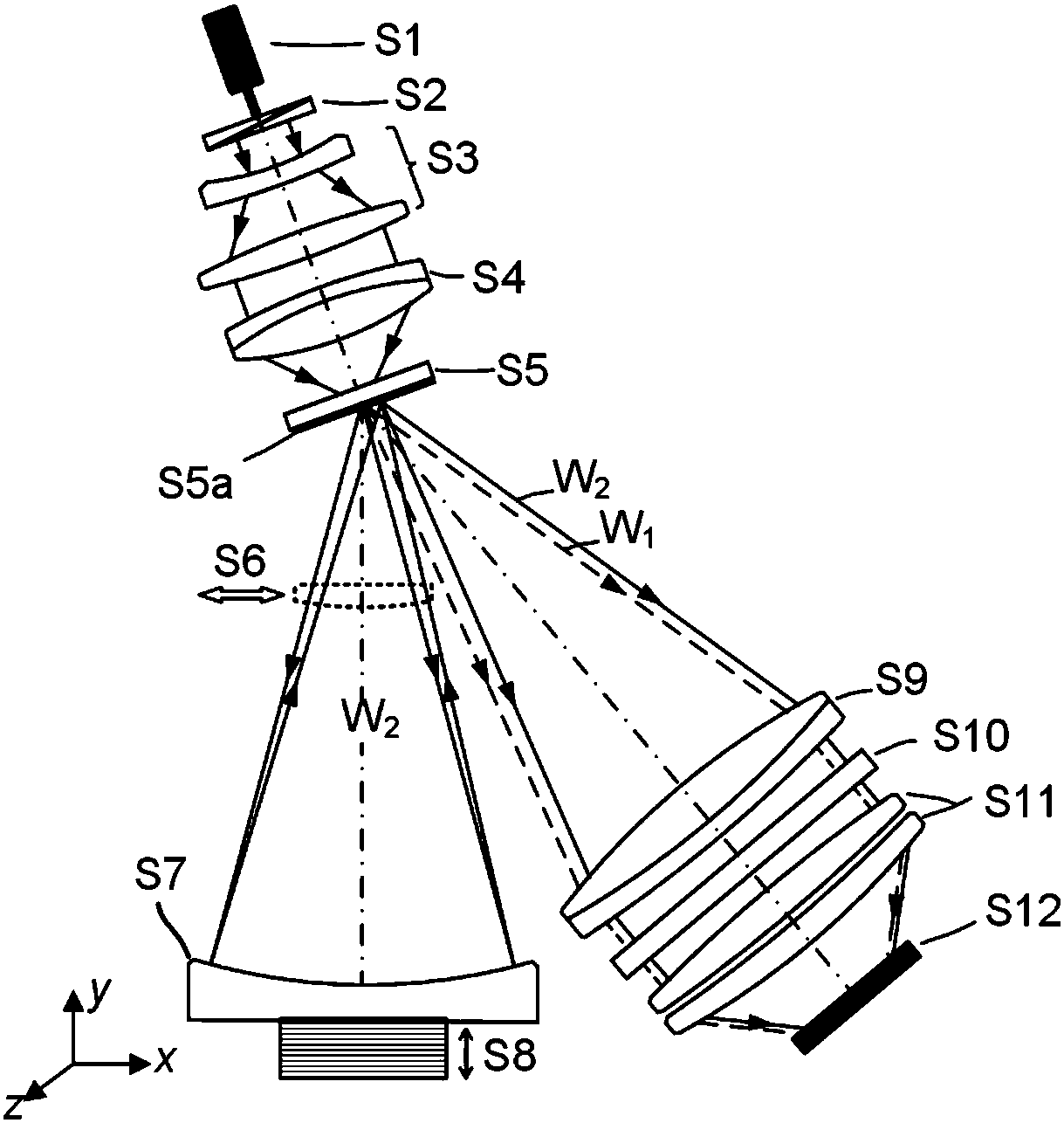
However, since the detection optical path is not a collimated plane wave but a divergent spherical wave, the quarter-wave plate will introduce large wavefront distortion aberration and polarization aberration in the surface shape detection
At the same time, the position of the wave plate needs to be adjusted according to the numerical aperture of the mirror to be tested, so it is easy to introduce random adjustment errors, increase the cumbersomeness of assembly and adjustment, and reduce the detection efficiency

Method used


Image

  • Wave plate design and error correction method in contrast ratio adjustable point diffraction interference system
  • Wave plate design and error correction method in contrast ratio adjustable point diffraction interference system
  • Wave plate design and error correction method in contrast ratio adjustable point diffraction interference system

Examples


Embodiment

[0065] The present invention is applied to the design of an even-order aspheric quarter-wave plate in a contrast-adjustable point diffraction interference system and an example of an error correction method is described as follows.

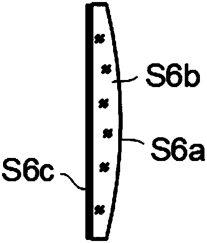
[0066] The wave plate is an even-order aspheric quarter-wave plate, and the even-order aspheric quarter-wave plate includes a plano-convex lens base whose convex surface is an even-order aspheric surface and a silicon dioxide polarizing film layer coated on the plane. The material of the plano-convex lens is K9 glass (refractive index n=1.51630), the center thickness is 1 mm, and the radius of curvature of the aspheric vertex is 500 mm.

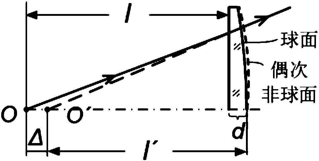
[0067] A ray tracing model was established to solve the structural parameters of the plano-convex lens substrate. First, the position of the image point after the paraxial light emitted by the pinhole passes through the base of the plano-convex lens is calculated by Gaussian formula. Since the pinhole diffractio...


PUM

PropertyMeasurementUnit
Center thicknessaaaaaaaaaa

Abstract

The invention discloses a wave plate design and error correction method in a contrast ratio adjustable point diffraction interference system. The light beam polarization state is adjusted in the modeof placing a quarter wave plate in a detection path, and then the interference stripe contrast ratio is adjustable. The problem is solved that when the wave plate is placed in a divergence spherical wave, a large wavefront error is generated. The wave plate design and error correction method is characterized in that that a flat and convex glass substrate of which the convex face is a non-sphericalface is adopted for the wave plate, and a plane is plated with a polarization membrane layer. Through even-order non-spherical design of the wave plate substrate, a wavefront distortion aberration caused when a large numerical value aperture sphere is detected is greatly lowered. By building a difference recovery model, a pose error generated on the wave plate is corrected. Since the even-order non-spherical quarter wave plate is fixed in design position in the detection path, after the pose error is corrected, the position of the wave plate does not need to be adjusted according to the change of the aperture numerical value of a mirror to be detected. The point diffraction system is easy to adjust, and the detection efficiency is improved.

Description

technical field [0001] The invention belongs to the field of optics, and relates to a wave plate design and error correction method in a point diffraction interference system with adjustable contrast. Background technique [0002] Among many optical detection methods, the point diffraction interferometer generates an ideal spherical wave as a reference wavefront by means of wavelength-scale microhole diffraction, without being limited by the processing accuracy of the standard reference mirror in the traditional interferometer, and can achieve better than sub- Nanoscale detection accuracy has become one of the most promising high-precision detection methods. The pinhole point diffraction interferometer uses pinholes to obtain ideal spherical waves, and uses part of the diffracted wavefront as a reference wavefront, and the other part as a detection wavefront, thereby achieving high-precision detection of spherical surface shape. However, if the light intensity of the diffra...

Claims


Application Information

Patent Timeline
IPC IPC(8): G01B9/02
CPCG01B9/02G01B9/02056
Inventor 杨甬英李瑶陈元恺王晨
Owner ZHEJIANG UNIV
Learn More