
Common-path radial shear interferometer based on four-step spatial digital phase-shift

A shearing interferometer and ring-direction shearing technology, applied in optics, instruments, scientific instruments, etc., can solve the problems of environmental vibration sensitivity, low measurement accuracy, and low contrast of interference fringes

Inactive Publication Date: 2013-04-03
INST OF OPTICS & ELECTRONICS - CHINESE ACAD OF SCI
View PDF4 Cites 0 Cited by
  • Summary
  • Abstract
  • Description
  • Claims
  • Application Information

AI Technical Summary

Problems solved by technology

[0004] James Notaras et al described in the article "Demonstration of closed-loop adaptive optics with a point-diffraction interferometer in strong scintillation with optical vortices" Optics Express. For the adaptive optics system of the wavefront sensor, due to the existence of the pinhole filter, the light energy utilization rate of the system is not high, and the contrast of the obtained interference fringes is low, which limits the wavefront detection accuracy; at the same time, the wavefront of the reference beam is not a plane wave This also makes the single wavefront measurement accuracy of the system not high, and the non-common path between the reference beam and the beam to be measured will also make the system more sensitive to environmental vibrations

Method used


Image

  • Common-path radial shear interferometer based on four-step spatial digital phase-shift
  • Common-path radial shear interferometer based on four-step spatial digital phase-shift
  • Common-path radial shear interferometer based on four-step spatial digital phase-shift

Examples


Embodiment Construction

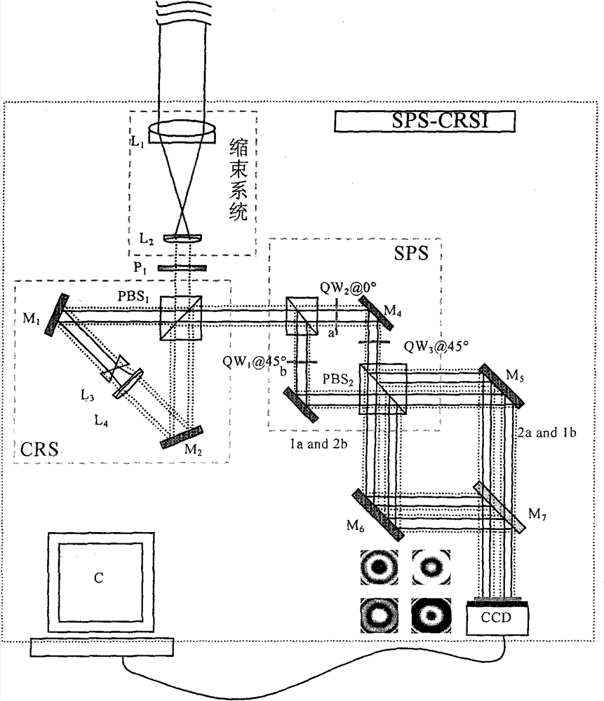
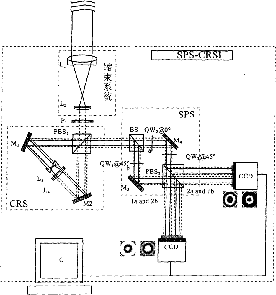
[0047] like figure 1 As shown, the distorted beam enters the common optical path direction shearing interferometer based on four-step spatial phase shifting, and the beam aperture is transformed by using the beam shrinking system. The lens L 1 , L 2 The focal lengths are f 1 and f 2 , the incident distorted beam aperture is A 1 , then the reduced beam aperture A 2 , and A 2 =A 1 f 2 / f 1 . Polarizer P 1 To adjust the light intensity of the polarized component of the reduced beam along the horizontal and vertical directions, set P 1 The polarizing angle is θ, then the light intensity ratio η of the polarization component along the horizontal direction and the vertical direction 1 like

[0048] (16) formula shows:

[0049] n 1 =1 / tanθ (16)

[0050] After the modulated beam enters the circular shearing system (CRS), it first passes through the polarizing beam splitter PBS 1 Divided into reflected linearly polarized light B vibrating in the horizontal direction ||...


PUM


Abstract

The invention relates to a common-path radial shear interferometer based on four-step spatial digital phase-shift. The interferometer comprises a light beam contraction system, a polarizer, a loop radial shear system CRS, a four-step spatial digital phase-shift system SPS, a light beam layout system, a CCD and a computer, wherein aberrated light beam enters a wave front sensor, the light beam contraction system is used to change the aperture of light beam, the polarizer is used to modulate the polarization direction of light beam; then the light beam enters the loop radial shear system to form two beams of light which have the same optic axis and perpendicular polarization directions, the apertures of the light beams are reduced or increased according to a same ratio; and the two beams oflight enter the four-step spatial digital phase-shift system to be divided into four pairs of coaxial light beams, each pair of coaxial light beams has the same polarization direction and the phase differences of fours pairs of coaxial light beams are 0, pi / 2, pi, 3pi / 2 in turn; and after the fours pairs of coaxial light beams are light beam layout, the fours pairs of coaxial light beams enter the photosensitive surface of the CCD at the same time to form four radial shear interference patterns, and the computer performs twice matrix manipulations according to the data of the four interference patterns so as to recover the distortion wave front of the light beam to be tested. The invention expands the application field of the wave front sensor adopting interference method and has obvious superiority.

Description

technical field [0001] The invention relates to a wavefront sensor for wavefront measurement based on interferometry, in particular to a wavefront sensor based on ring-direction shear-four-step space phase shift interferometry (CRS-SPS). Background technique [0002] Currently in adaptive optics systems, Hartmann wavefront sensors are widely used. In order to improve the measurement accuracy, it is necessary to increase the number of sub-apertures of the Hartmann wavefront sensor, and each sub-aperture corresponds to a certain number of CCD pixels. Therefore, more pixels are required on the CCD target surface, and a relatively large number of CCD cameras is proposed. high demands. [0003] In the self-referencing wavefront sensor based on ring path shear-four-step space phase shift interferometry, each pixel on the CCD target surface can be regarded as a sub-aperture, so that each pixel can directly correspond to a part of the wavefront, When the incident wavefront apertur...

Claims


Application Information

Patent Timeline
Patent Type & Authority Patents(China)
IPC IPC(8): G02B26/00G01J9/02G02B26/06
Inventor 顾乃庭白福忠黄林海杨泽平饶长辉
Owner INST OF OPTICS & ELECTRONICS - CHINESE ACAD OF SCI
Learn More