
Magnetic isolation type multi-circuit synchronous trigger circuit with negative voltage bias

A multi-channel synchronization and trigger circuit technology, applied in electrical components, output power conversion devices, AC power input into DC power output and other directions, can solve problems such as limiting pulse frequency, reduce size, optimize electromagnetic environment, reduce The effect of complexity

Inactive Publication Date: 2018-08-03
UNIV OF SHANGHAI FOR SCI & TECH
View PDF5 Cites 6 Cited by
  • Summary
  • Abstract
  • Description
  • Claims
  • Application Information

AI Technical Summary

Problems solved by technology

Only when the load charge is fully released can the next discharge be effectively carried out, which severely limits the pulse frequency
Studies have shown that the square wave high-voltage pulse provides a short-circuit channel for the dielectric barrier discharge load at the pulse trailing edge, causing its residual voltage to drop to zero quickly. The reverse discharge current will generate a secondary discharge and improve the discharge efficiency. The wave Marx generator came into being, but there is no driving circuit suitable for the square wave Marx generator

Method used


Image

  • Magnetic isolation type multi-circuit synchronous trigger circuit with negative voltage bias
  • Magnetic isolation type multi-circuit synchronous trigger circuit with negative voltage bias
  • Magnetic isolation type multi-circuit synchronous trigger circuit with negative voltage bias

Examples


Embodiment

[0028] The invention provides a magnetically isolated multi-channel synchronous trigger circuit with negative voltage bias, and the technical scheme is as follows:

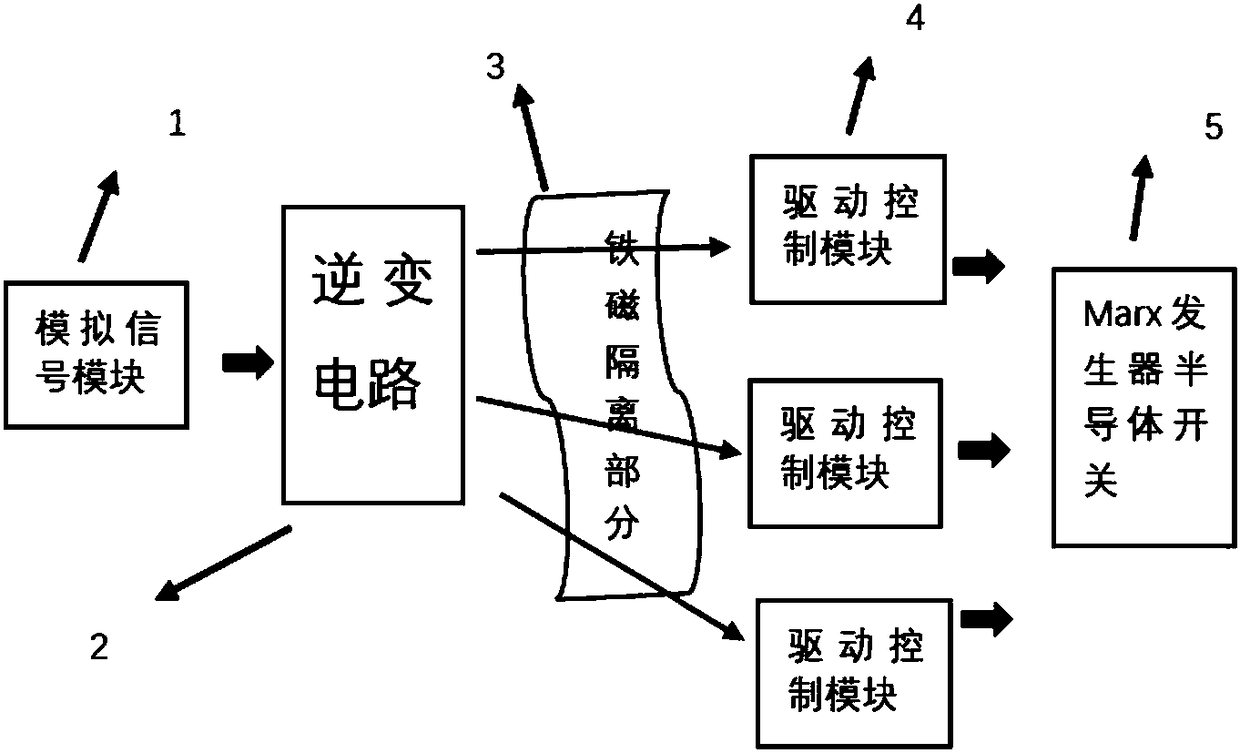
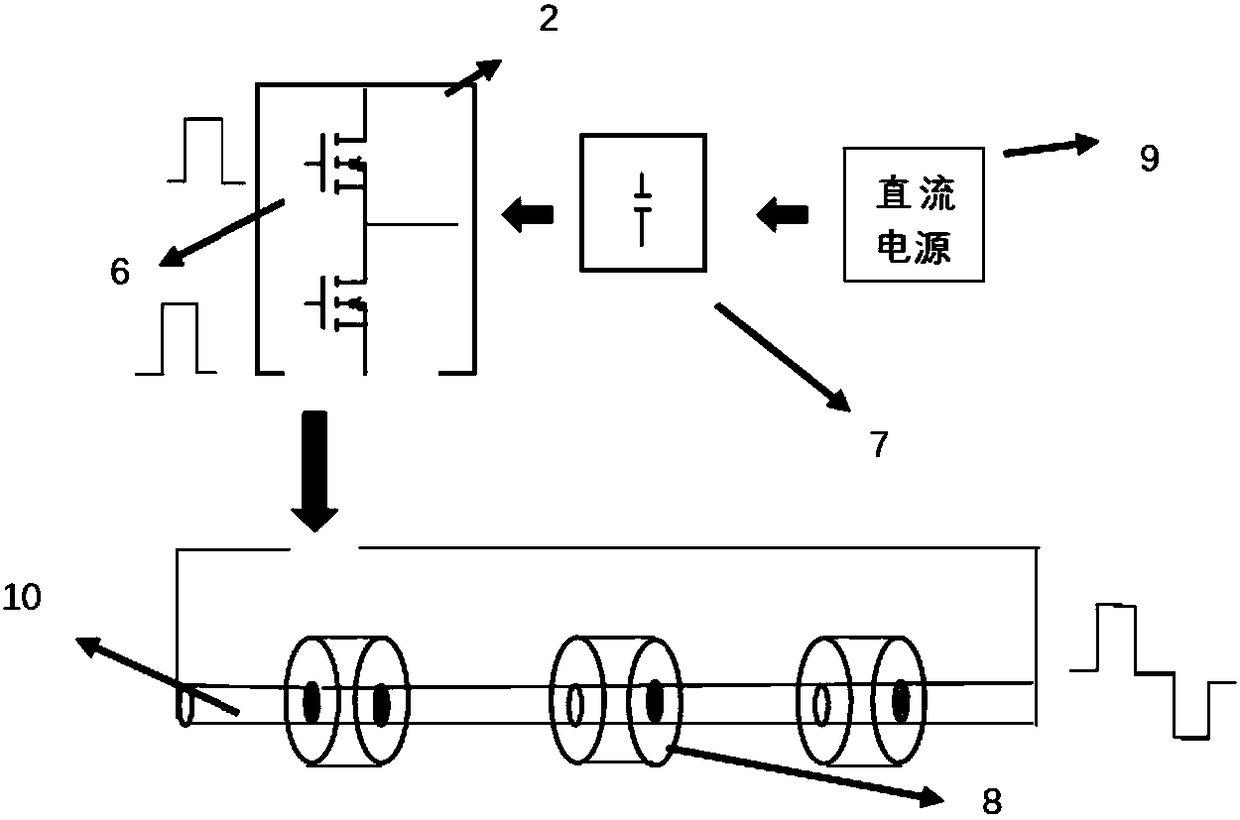
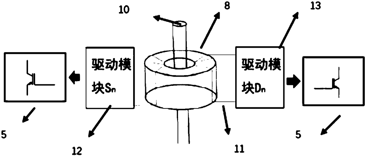
[0029] Firstly, an analog signal is generated in the central control part, which can control the pulse width, phase and frequency of the driving signal, and the output signal controls the on-off of the switch tube in the inverter circuit. The switch tube can use MOSFET and IGBT, etc., thereby generating a dual Polar voltage waveform, the load end of which is penetrated into the magnetic core hole of the ferromagnetic isolation part through the connecting wire as the primary side, so as to achieve the purpose of sharing the primary side of multiple transformers.

[0030] Thereafter, since the multi-stage magnetic core is penetrated in series, it has the function of voltage division, so the magnetic isolation transformer can use the boost mode to increase the voltage amplitude of the output signal on the secondary si...


PUM


Abstract

The invention relates to a magnetic isolation type multi-circuit synchronous trigger circuit with negative voltage bias. The multi-circuit synchronous trigger circuit comprises a primary side drivingcircuit used for generating positive and negative dual-polarity pulse signals, a magnetic isolation transformer, secondary side driving control modules and a plurality of controlled semiconductor switches; and the primary side coil of the magnetic isolation transformer is connected with the primary side driving circuit while the secondary side coil generates synchronous driving signals of different time sequences through the multiple secondary side driving control modules to drive the controlled semiconductor switches. Compared with the prior art, the multi-circuit synchronous trigger circuithas the advantages of improving of driving efficiency, lowering of complexity, providing of negative voltage bias and the like.

Description

technical field [0001] The invention relates to the technical field of pulse modulation, in particular to a magnetically isolated multi-channel synchronous trigger circuit with negative voltage bias. Background technique [0002] In the field of pulse modulation technology, high-voltage pulse output is often achieved through series-parallel technology of switching tubes. Therefore, multiple switching tubes need to be driven synchronously, and multiple groups of switching tubes need to be turned on and off to realize pulse waveform modulation. , to output different pulse waveforms. [0003] In the common synchronous driving scheme, under the condition of using iron core isolation, the pulse width of the driving signal is greatly affected due to the saturation of the magnetic core. [0004] In the high-voltage pulse power supply, because the output pulse has a fast voltage or current front, it will generate strong electromagnetic interference, which will cause the false trigg...

Claims


Application Information

Patent Timeline
Patent Type & Authority Applications(China)
IPC IPC(8): H02M1/088H02M7/537
CPCH02M1/088H02M7/537H02M1/0006
Inventor 饶俊峰刘昊天姜松李孜
Owner UNIV OF SHANGHAI FOR SCI & TECH
Learn More