

Organic rankine cycle air inflow supercharging internal combustion engine system and method
A Rankine cycle, intake boosting technology, applied in the direction of internal combustion piston engine, machine/engine, mechanical equipment, etc., can solve the problems of complicated system and large heat loss, achieve high efficiency and environmental protection of the system, small loss of working power, The effect of small heat exchange temperature difference
- Summary
- Abstract
- Description
- Claims
- Application Information
AI Technical Summary
Problems solved by technology
Method used
Image

Examples
Embodiment 1
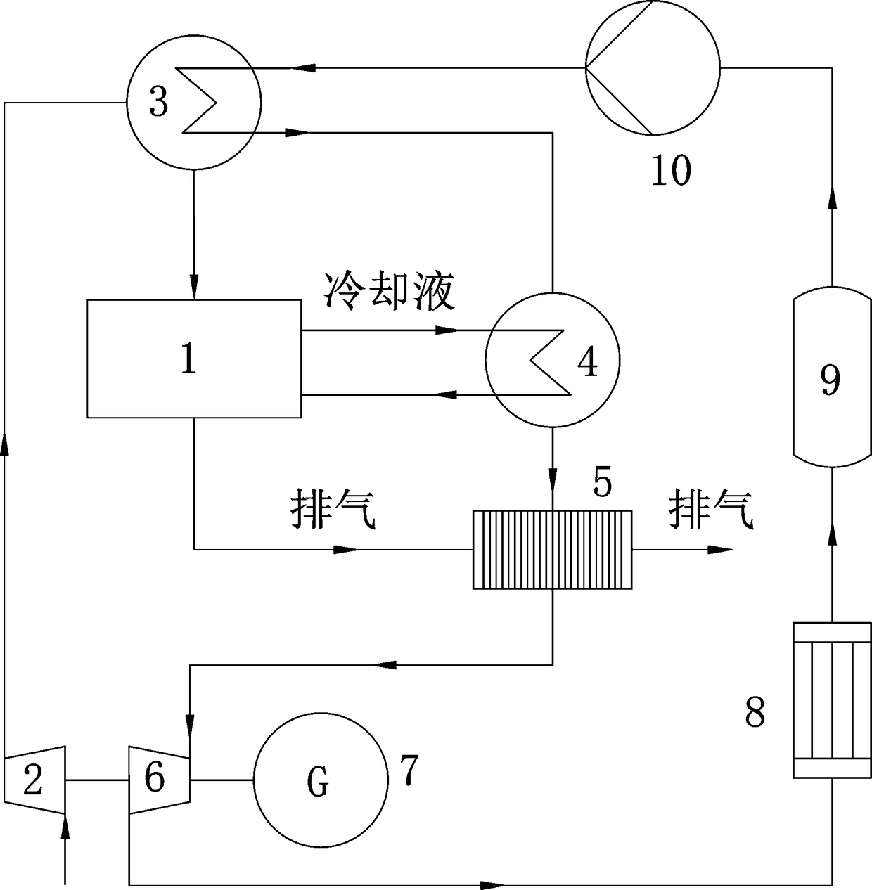
[0025] Such as figure 1 as shown, figure 1 It is a schematic diagram of the overall structure of the system. The organic Rankine cycle air intake supercharged internal combustion engine system, the organic Rankine cycle is ORC, including: internal combustion engine 1, compressor 2, intercooler 3, preheater 4, evaporator 5, expander 6 , generator 7, condenser 8, liquid storage tank 9 and working medium pump 10.
[0026] The inlet of compressor 2 is connected to the outside air, the outlet of compressor 2 is connected to the first inlet of intercooler 3, the first outlet of intercooler 3 is connected to the inlet of internal combustion engine 1, and the second inlet of intercooler 3 is connected to the outlet of working medium pump 10 , the second outlet of the intercooler 3 is connected to the inlet of the preheater 4, the preheater 4 is connected to the second inlet of the evaporator 5, the exhaust outlet of the internal combustion engine 1 is connected to the first inlet of ...
Embodiment 2
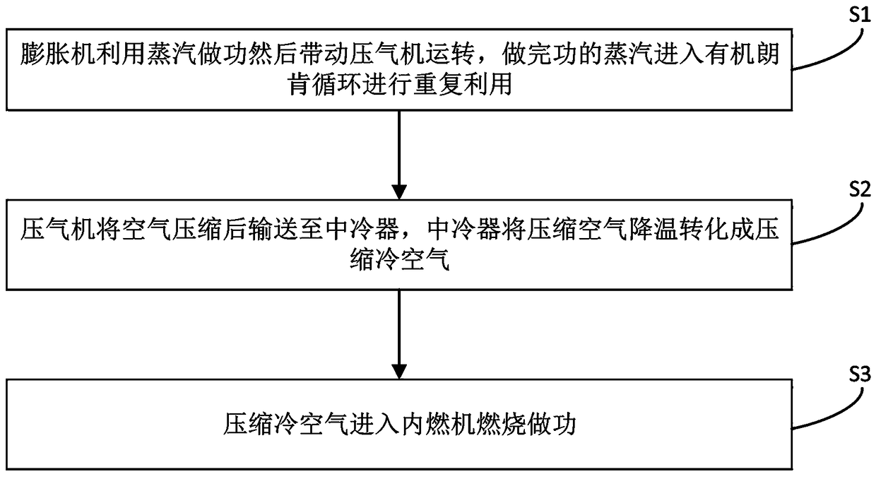
[0035] Such as figure 2 As shown, an organic Rankine cycle air intake supercharging method includes the following steps:
[0036] S1: The expander uses the steam to do work and then drives the compressor to run, and the steam that has done the work enters the organic Rankine cycle system for reuse.
[0037] The second outlet of the evaporator 5 is connected to the inlet of the expander 6, the expander 6 is respectively connected to the compressor 2 and the generator 7, the outlet of the expander 6 is connected to the inlet of the condenser 8, and the outlet of the condenser 8 is connected to the inlet of the liquid storage tank 9 , the outlet of the liquid storage tank 9 is connected with the inlet of the working fluid pump 10 . From this structure, it can be seen that the organic working medium absorbs heat in the evaporator 5 and becomes saturated steam or superheated steam, and then enters the expander 6 to expand and perform work. Part of the mechanical work output by t...
PUM
 Abstract
Description
Claims
Application Information