

Detonation gun spraying device and detonation gun spraying technology
A technology of explosive spraying and explosive wave, which is applied in the direction of metal material coating process, coating, molten spraying, etc., can solve the problems of restricting the scope of application of explosive spraying, high noise, etc., and achieve the simplification of explosive spraying equipment and ancillary facilities, safety High performance and wide application range
- Summary
- Abstract
- Description
- Claims
- Application Information
AI Technical Summary
Problems solved by technology
Method used
Image

Examples
Embodiment 1
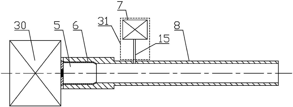
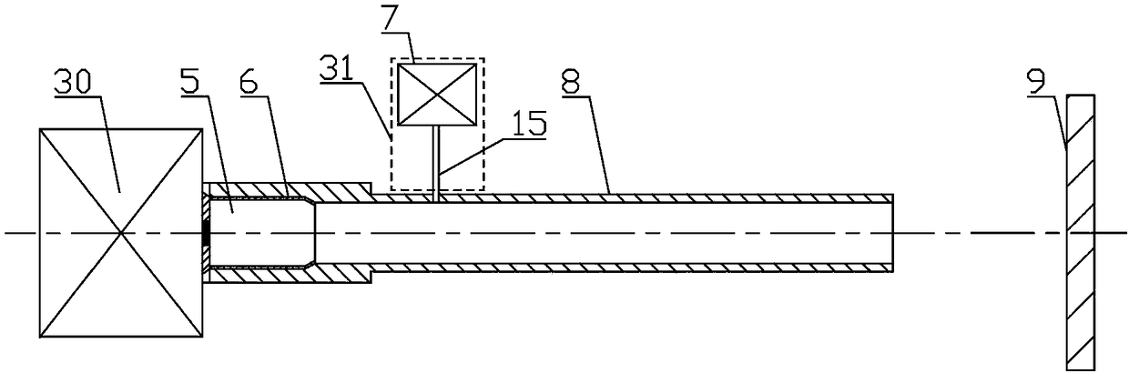
[0053] A kind of detonation spraying device is provided among the present embodiment, comprises launching unit 30, spray pipe 8 and projectile body 5, as figure 1 As shown, wherein, the nozzle 8 is a hollow tube, and one end of the nozzle 8 is the body chamber 6, and the body chamber 6 is used to accommodate the body 5, and the nozzle 8 is connected with a powder supply unit 31; the powder supply unit 31 For conveying the spraying powder 13 in the spray pipe 8, the launching unit 30 is connected on the projectile chamber 6, and the launching unit 30 is used to detonate the projectile 5 in the projectile chamber 6, and the explosion wave generated by the projectile 5 explosion is generated in the spray pipe. 8 , heat the spray powder 13 and push the spray powder 13 toward the workpiece 9 to form a coating 14 .
[0054] The projectile 5 in the explosive spraying device can be a solid propellant, a nail-shooting projectile, or a bullet after the warhead has been removed and seale...
Embodiment 2
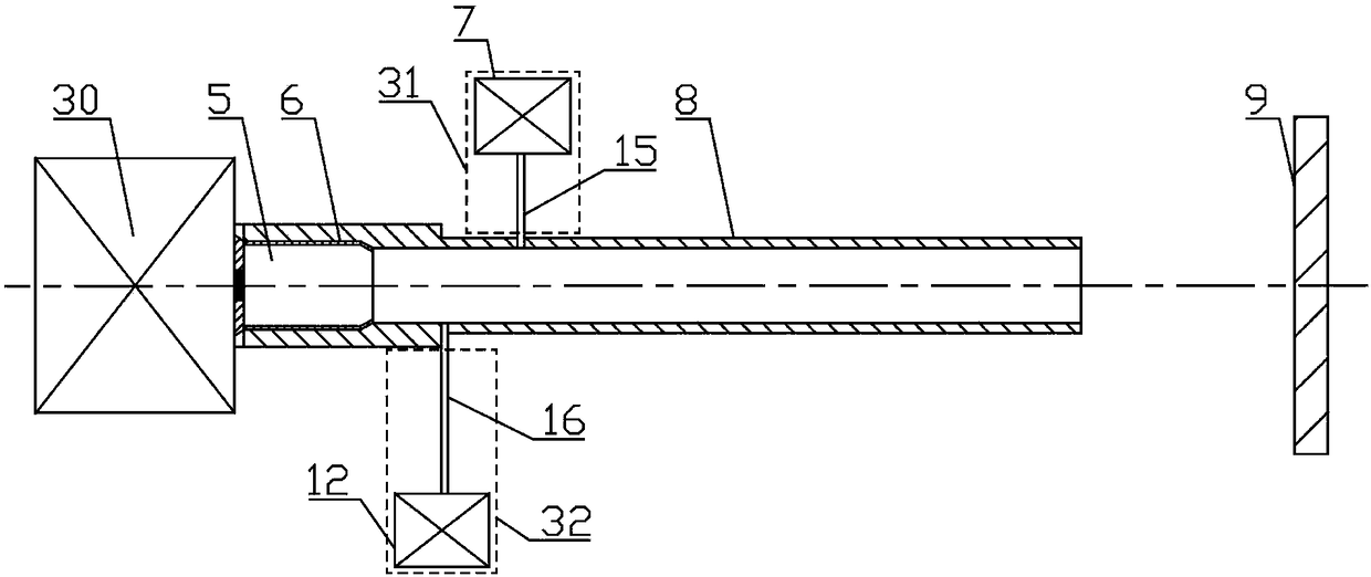
[0065] The main difference between this embodiment 2 and the above-mentioned embodiment 1 is that in this embodiment, a specific structure of a launching unit 30 suitable for the above-mentioned explosive spraying device is provided, such as Figure 4 As shown, in this embodiment, the launching unit 30 includes a firing device, a recoil device and an extracting device 11, wherein,
[0066] The recoil device comprises recoil spring 3, recoil device 4, guide pipe 10, and guide pipe 10 is a hollow circular tube, and the two ends of guide pipe 10 are respectively connected firing device and the projectile chamber 6 of nozzle pipe 8, recoil spring 3 and the recoiler 4 are respectively arranged in the guide tube 10, and the two ends of the recoil spring 3 are respectively connected with the firing device and the recoiler 4, and the recoiler 4 is provided with a through hole along the axial direction of the guide tube 10, and the recoiler The outer diameter of the device 4 is smaller t...
Embodiment 3
[0078] The main difference between this embodiment 3 and the above-mentioned embodiment 2 is that in this embodiment, the explosive spraying device also includes a projectile 5 supply unit, and the projectile 5 supply unit is connected to the launch unit 30, and several The projectiles 5 can also send the projectiles 5 into the launching unit 30 one by one. A plurality of projectile bodies 5 can be stored in the projectile body 5 supply unit, and one projectile body 5 can carry out explosive spraying, and the projectile body 5 supply unit can send projectile bodies 5 into the launching unit 30 one by one; At the same time, it is convenient for continuous spraying, which can effectively improve the spraying efficiency.
[0079] Such as Figure 16 As shown, in this embodiment, the projectile body 5 supply unit includes a magazine 20, the magazine 20 is used to store the projectile 5, and the magazine 20 is provided with a delivery spring 21, and the magazine 20 is connected to ...
PUM
| Property | Measurement | Unit |
|---|---|---|
| The inside diameter of | aaaaa | aaaaa |
| Length | aaaaa | aaaaa |
Abstract
Description
Claims
Application Information