
Seabed combustible ice detector and detection method thereof

A detection method and detector technology, applied in the field of detectors, can solve problems such as the inability to provide accurate positions of combustible ice, and achieve the effects of enhanced detection flexibility, compact overall structure, and high mobility

Inactive Publication Date: 2018-08-10
XIAN UNIV OF TECH
View PDF5 Cites 1 Cited by
  • Summary
  • Abstract
  • Description
  • Claims
  • Application Information

AI Technical Summary

Problems solved by technology

[0005] The purpose of the present invention is to provide a detector for combustible ice on the seafloor, which solves the problem that the existing detector cannot provide the precise position of combustible ice

Method used


Image

  • Seabed combustible ice detector and detection method thereof
  • Seabed combustible ice detector and detection method thereof
  • Seabed combustible ice detector and detection method thereof

Examples


Embodiment Construction

[0055] The present invention will be described in detail below in conjunction with the accompanying drawings and specific embodiments.

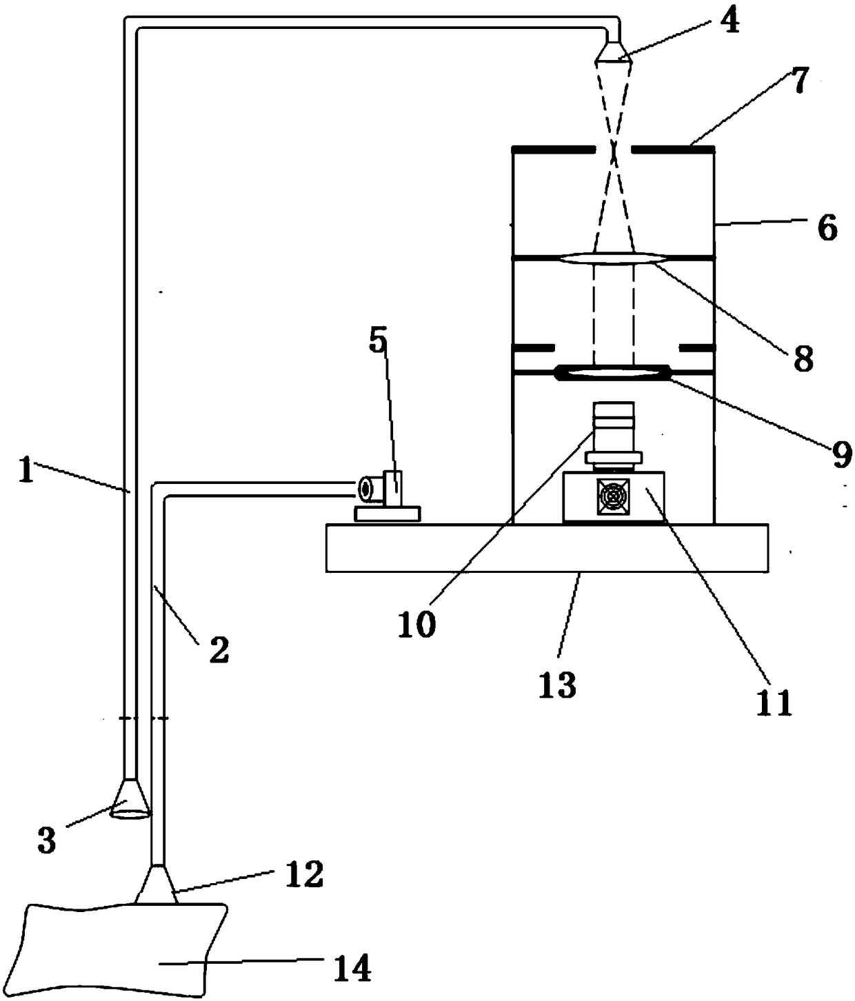
[0056] A kind of seabed combustible ice detector of the present invention, such as figure 1 As shown, it includes an optical fiber a1 and an optical fiber b2, one end of the optical fiber a1 is provided with an optical port a3, the other end of the optical fiber a1 is connected with a beam expander 4, one end of the optical fiber b2 is connected with a laser 5, and the other end of the optical fiber b2 is connected with an optical port b12, The light port b12 contacts the combustible ice 14 on the seabed;

[0057] The top of the housing 6 is provided with a field diaphragm 7, and the housing 6 is sequentially provided with a Fresnel lens 8, an interference filter 9, an imaging lens 10, and a CCD camera 11 from top to bottom; the position and field of view of the beam expander 4 The diaphragm 7 also includes an optical platform 13 on which th...


PUM

PropertyMeasurementUnit
Bandwidthaaaaaaaaaa

Abstract

The invention discloses a seabed combustible ice detector comprising an optical fiber a and an optical fiber b. One end of the optical fiber a is provided with a light transmission port a, and the other end of the optical fiber a is connected with a beam expander. One end of the optical fiber b is connected with a laser, and the other end of the optical fiber b is connected with a light transmission port b. The seabed combustible ice detector also comprises a shell. The top part of the shell is provided with a field diaphragm. The shell is internally provided with a Fresnel lens, an interference light filter, an imaging lens and a CCD camera which are arranged from the top to the bottom in turn. The detection method comprises the following concrete steps: step 1, the target information ofthe seabed is acquired; step 2, two spectral lines are selected from the imaging interference fringes obtained on the CCD camera in the step 1, the light intensity of the spectrum is detected on the CCD camera and the relative intensity S of the spectral lines is acquired from an HITRAN synthetic spectrum database; and step 3, the temperature, the pressure intensity and the molecular number density of the combustible ice, i.e. the characteristic parameters of the combustible ice, are calculated according to the light intensity and the relative intensity S of the spectral lines acquired throughthe step 2. Higher frequency and more accurate position determination of seabed combustible ice detection can be realized.

Description

technical field [0001] The invention belongs to the technical field of detectors, and relates to a detector for combustible ice on the seabed, and also relates to a detection method of the detector. Background technique [0002] At present, the methods commonly used in the world to detect combustible ice include: geophysical method, seismic survey method, marine controlled electromagnetic prospecting method, logging core analysis method, seabed visual detection method, geochemical prospecting method, etc. Among them, seismic processing and imaging techniques in geophysical methods are most widely used. In marine exploration, the seismic pseudo-bottom simulating reflection layer BSR (Bottom Simulating Reflection) is often used as a sign of the presence of combustible ice [1,2] . Geophysical method and AVO (Amplitude Versus Offset) analysis technology [3] , Velocity field establishment technology (using the difference in propagation speed of seismic waves in combustible ice...

Claims


Application Information

Patent Timeline
IPC IPC(8): G01V8/02G01V8/10
CPCG01V8/02G01V8/10
Inventor 唐远河王浩轩
Owner XIAN UNIV OF TECH
Learn More