
Composite die master die as well as manufacturing method and application thereof

A composite material and manufacturing method technology, applied in the field of composite material mold manufacturing, can solve the problems of layer material deformation, difficulty in layer laying, size deviation, etc., and achieve the effects of high mold precision, increased working strength, and good temperature resistance

Active Publication Date: 2018-08-17
TIANJIN ISTAR-SPACE TECH CO LTD
View PDF3 Cites 10 Cited by
  • Summary
  • Abstract
  • Description
  • Claims
  • Application Information

AI Technical Summary

Problems solved by technology

[0005] However, the composite material molds produced in the prior art still have the following problems: the temperature resistance level of the master mold is insufficient, and it is easy to collapse during the vacuum infusion process; the surface of the composite material mold is not beautiful, and the cost is high; Difficulty in laying layers; insufficient resin infusion due to material problems; internal stress caused by differences in expansion coefficients of different materials in stroke molds, resulting in dimensional deviations, cracks on the surface, and damage to the mold, etc.

Method used


Image

  • Composite die master die as well as manufacturing method and application thereof
  • Composite die master die as well as manufacturing method and application thereof
  • Composite die master die as well as manufacturing method and application thereof

Examples


preparation example 1

[0082] The preparation of preparation example 1 master model

[0083] This preparation example is carried out in the following way:

[0084] (1) Weld a steel frame (model Q235) with a size of 6000*2500*10mm, and make a steel frame and stack steel bars (45#) on the steel frame to form a steel profile, and then conduct heat treatment at a temperature of 140°C 3 hours.

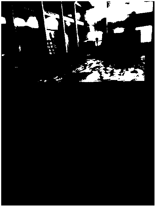
[0085] (2) Lay a wood layer with a thickness of 20mm on the steel surface to form a wood layer surface (such as figure 2 shown), thereby eliminating the gap between the steel frames;

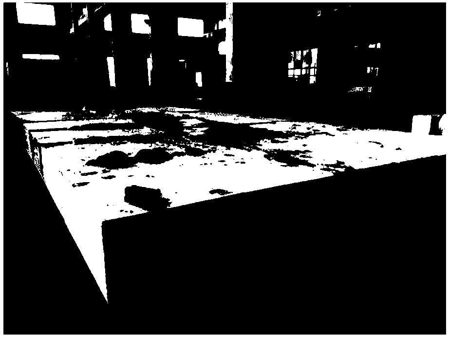
[0086] (c) Adhere a polyurethane foam layer with a thickness of 10mm on the surface of the plank layer and rough machine it until the surface accuracy is about ±3mm to form a rough machined surface; image 3 Prepare site photos for the master model with foam.

[0087] (d) Lay a FRP layer with a thickness of about 5 mm on the foam surface to form a FRP layer profile; then polish the FRP layer to roughen the surface so that the ...

preparation example 2

[0090] It was carried out in substantially the same manner as in Preparation Example 1, except that PS (polystyrene foam) foam was used instead of polyurethane foam.

preparation example 3

[0092] The method was basically the same as that of Preparation Example 1, except that PMI (purchased from Zhejiang Zhongke Hengtai New Material Technology Co., Ltd.) foam was used instead of polyurethane foam.


PUM

PropertyMeasurementUnit
Thicknessaaaaaaaaaa
Thicknessaaaaaaaaaa
Thicknessaaaaaaaaaa

Abstract

The invention relates to a composite die master die as well as a manufacturing method and application thereof. The method comprises the following steps of manufacturing a steel frame, and stacking steel strips on the steel frame to form a steel profile; laying a wood slab layer on the steel profile to form a wood slab layer profile; adhering a foam layer to the wood slab layer profile, and performing rough machining to form a roughly machined profile; laying a glass fiber reinforced plastic layer on the foam profile to form a glass fiber reinforced plastic layer profile; and laying a wood substituted resin layer on the glass fiber reinforced plastic layer profile, and performing finish machining to obtain the master die with a finish machined profile. The invention also provides the masterdie manufactured by the method and application of the master die in manufacturing a composite die. The method has the advantages of low cost, small processing difficulty, short production period andthe like; and the manufactured master die and the manufactured composite die have the advantages of good temperature resistance, high die accuracy, light weight and the like, overcome the problems ofsurface cracks, deformation and the like of a traditional composite die and have large potential market in the field of aircraft and vehicle manufacturing and the like.

Description

technical field [0001] The invention relates to the field of composite material mold manufacturing, in particular to a composite material mold mother mold, a composite material mold and a manufacturing method and application thereof. Background technique [0002] In recent years, aerospace, weapons, ships, high-speed rail and other industries have developed rapidly. Lightweight and low-carbon and high-efficiency are the themes of the development of the times. Composite materials replacing traditional metal materials are an important development direction for military-civilian and military-civilian integration. There are some insurmountable technical gaps in the development of large and complex composite components. The long development cycle is also a rigid obstacle to its expansion. The high cost of mold manufacturing has seriously affected the wide application of composite materials. [0003] In recent years, while the wave of wind power blades has gradually receded, the d...

Claims


Application Information

Patent Timeline
IPC IPC(8): B29C70/36B29C70/54B29C33/38
CPCB29C33/3828B29C33/3842B29C70/36B29C70/54B29C2033/385
Inventor 段轶锋
Owner TIANJIN ISTAR-SPACE TECH CO LTD
Learn More