Fiber surface interface layer deposition equipment and method

A fiber surface and interface layer technology, applied in fiber treatment, coating, metal material coating process, etc., can solve problems such as low efficiency, too thin interface layer, difficult to control diffusion, etc., achieve high utilization rate, avoid damage, The effect of improving safety

A fiber surface and interface layer technology, applied in fiber treatment, coating, metal material coating process, etc., can solve problems such as low efficiency, too thin interface layer, difficult to control diffusion, etc., achieve high utilization rate, avoid damage, The effect of improving safety

CN108409348AActive Publication Date: 2018-08-17CENT SOUTH UNIV

Image

  • Fiber surface interface layer deposition equipment and method
  • Fiber surface interface layer deposition equipment and method
  • Fiber surface interface layer deposition equipment and method

Examples


Embodiment 1

[0082] The continuous SiC fiber was placed in a muffle furnace at 400°C for 30 minutes under air condition; that is, the pretreated SiC fiber bundle after degumming was obtained.

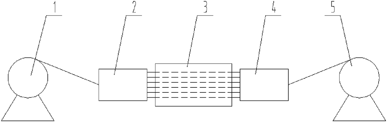
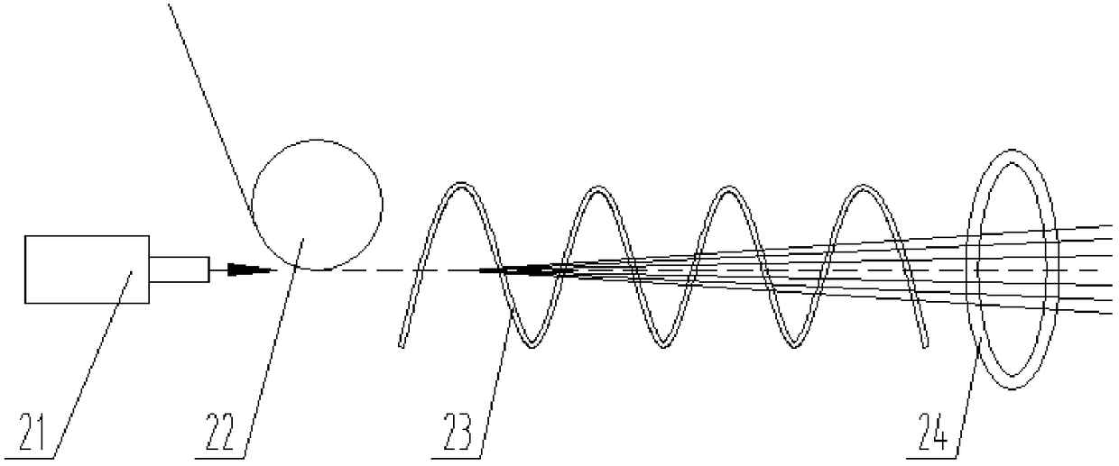
[0083] The SiC fiber bundle is released from the wire-feeding device and steered by the steering wheel between the electron emission gun and the magnetic induction coil. The steered SiC fiber bundle and the electron beam emitted by the electron emission gun form an angle of α, and the 0 °≤α≤5°, after the SiC fiber bundle enters the magnetic induction coil, the electron beam emitted by the electron gun makes the SiC fiber polarized with negative static electricity. The static electrostatic constriction ring O enters the magnetron sputtering device. Since the SiC fiber bundle is subjected to the Lorentz force and electrostatic repulsion in the magnetic induction coil and the electrostatic constricting ring, the fiber bundle will not be excessively dispersed, which not only enables the fiber to advance...

Embodiment 2

[0095] The continuous SiC fiber is kept in the air environment of a muffle furnace at a temperature of 500° C. for 15 minutes; that is, a pretreated SiC fiber bundle is obtained.

[0096] The SiC fiber bundle is released from the wire-feeding device and steered by the steering wheel between the electron emission gun and the magnetic induction coil. The steered SiC fiber bundle and the electron beam emitted by the electron emission gun form an angle of α, and the 0 °≤α≤5°, after the SiC fiber bundle enters the magnetic induction coil, the electron beam emitted by the electron gun makes the SiC fiber polarized with negative static electricity. The static electrostatic constriction ring O enters the magnetron sputtering device. Since the SiC fiber bundle is subjected to the Lorentz force and electrostatic repulsion in the magnetic induction coil and the electrostatic constricting ring, the fiber bundle will not be excessively dispersed, which not only enables the fiber to advance...

Embodiment 3

[0108]The continuous SiC fiber is kept in the air condition of a muffle furnace at a temperature of 600° C. for 10 minutes; that is, a pretreated SiC fiber bundle is obtained.

[0109] The SiC fiber bundle is released from the wire-feeding device and steered by the steering wheel between the electron emission gun and the magnetic induction coil. The steered SiC fiber bundle and the electron beam emitted by the electron emission gun form an angle of α, and the 0 °≤α≤5°, after the SiC fiber bundle enters the magnetic induction coil, the electron beam emitted by the electron gun makes the SiC fiber polarized with negative static electricity. The static electrostatic constriction ring O enters the magnetron sputtering device. Since the SiC fiber bundle is subjected to the Lorentz force and electrostatic repulsion in the magnetic induction coil and the electrostatic constricting ring, the fiber bundle will not be excessively dispersed, which not only enables the fiber to advance al...


PUM

PropertyMeasurementUnit
lengthaaaaaaaaaa
thicknessaaaaaaaaaa
lengthaaaaaaaaaa

Abstract

The invention discloses fiber surface interface layer deposition equipment and method. The equipment comprises a filament release device, an electrostatic filament scattering device, a magnetron sputtering device, a solid adhesive device and a filament collecting device. The filament collecting device and the filament release device are positioned on two sides of the magnetron sputtering device, the electrostatic filament scattering device is positioned between the filament release device and the magnetron sputtering device, and the solid adhesive device is positioned between the filament collecting device and the magnetron sputtering device. When the equipment is in operation, fiber bundles are released from the filament release device, then move to the electrostatic filament scattering device to be scattered, enter the magnetron sputtering device in a scattered state and are bundled by the solid adhesive device after an interface layer is obtained through magnetron sputtering deposition, and the fiber bundles are finally collected by the filament collecting device. The SiC fiber surface interface layer obtained according to the preparation method is uniform in thickness distribution, controllable in thickness and low in fiber damage and is a quasi-graphene structure weak interface layer, and mechanical performances of composite materials can be remarkably improved.

Description

technical field [0001] The invention relates to a device and a method for depositing an interface layer on a fiber surface, and belongs to the field of continuous fiber reinforced structural composite materials. Background technique [0002] SiC f / SiC composite material refers to the composite material with continuous SiC fiber as reinforcement and SiC ceramic as matrix. SiC f / SiC composite materials have excellent properties such as low density, high strength, high modulus, high temperature resistance, and oxidation resistance, and have broad application prospects in the fields of lightweight and high temperature resistance. In SiC f In SiC / SiC composites, the interface layer is the bridge between the braided fiber and the matrix material to transmit the load, and it is also the key factor for the preparation of continuous SiC fiber reinforced composites with excellent performance. In SiC f In / SiC composite materials, the ideal interface layer mainly has the followi...

Claims


Application Information

Patent Timeline
17 Aug 2018
Publication
CN108409348A
IPC
C04B35/80; C04B35/622; C04B35/565; C23C14/35; C23C14/06; C23C14/56; C23C14/02; D06M11/74; D06M11/77; D06M11/80; D06M11/79; D06M11/44; D06M11/53
CPC
C04B35/806; C04B35/565; C04B35/622; C04B2235/386; C04B2235/422; C04B2235/5244; C04B2235/96; C23C14/02
Inventors
阳海棠; 黄小忠