Mold and method for making joint sample for shear and seepage coupling test

A joint and seepage technology, which is applied in the field of rock mechanics and seepage mechanics, can solve problems such as troublesome disassembly, inaccurate test results, and poor side sealing, and achieve safe operation and good sample results

Inactive Publication Date: 2018-08-17
TONGJI UNIV +2
View PDF14 Cites 3 Cited by
  • Summary
  • Abstract
  • Description
  • Claims
  • Application Information

AI Technical Summary

Problems solved by technology

In addition, during the rock joint shear-seepage coupling test, the shape requirements of the joint specimen are relatively strict, generally a cuboid specimen of 100×100×200mm, which requires high dimensional accuracy and flat and parallel stress surfaces, otherwise During the loading process, there will be bias, joint specimens cannot be put into the shear seepage cell, and the sealing of the side is not good, resulting in inaccurate test results.
[0003] At present, there are two problems in the selection and production of materials for rock joint shear-seepage coupling tests: first, gypsum, cement mortar and other materials are often used to replicate rock joint surfaces, and their compressive strength is low, so high normal stress and high normal stress cannot be achieved. The joint shear-seepage coupling test under high water pressure cannot more realistically restore the mechanical properties of rock-like materials. Second, in the process of making joints, the degree of reduction of the roughness of the upper and lower joints is low, and the upper and lower joint surfaces are not complete. coupling (that is, the initial gap width of the joint surface is 0), and the size of the joint cannot be precisely controlled, and it is troublesome to install and disassemble during the test manufacturing process

Method used


Image

  • Mold and method for making joint sample for shear and seepage coupling test
  • Mold and method for making joint sample for shear and seepage coupling test
  • Mold and method for making joint sample for shear and seepage coupling test

Examples


Embodiment 1

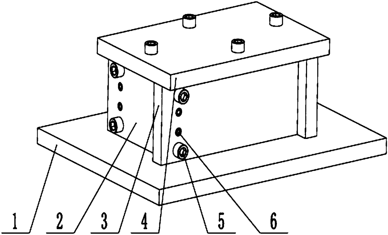
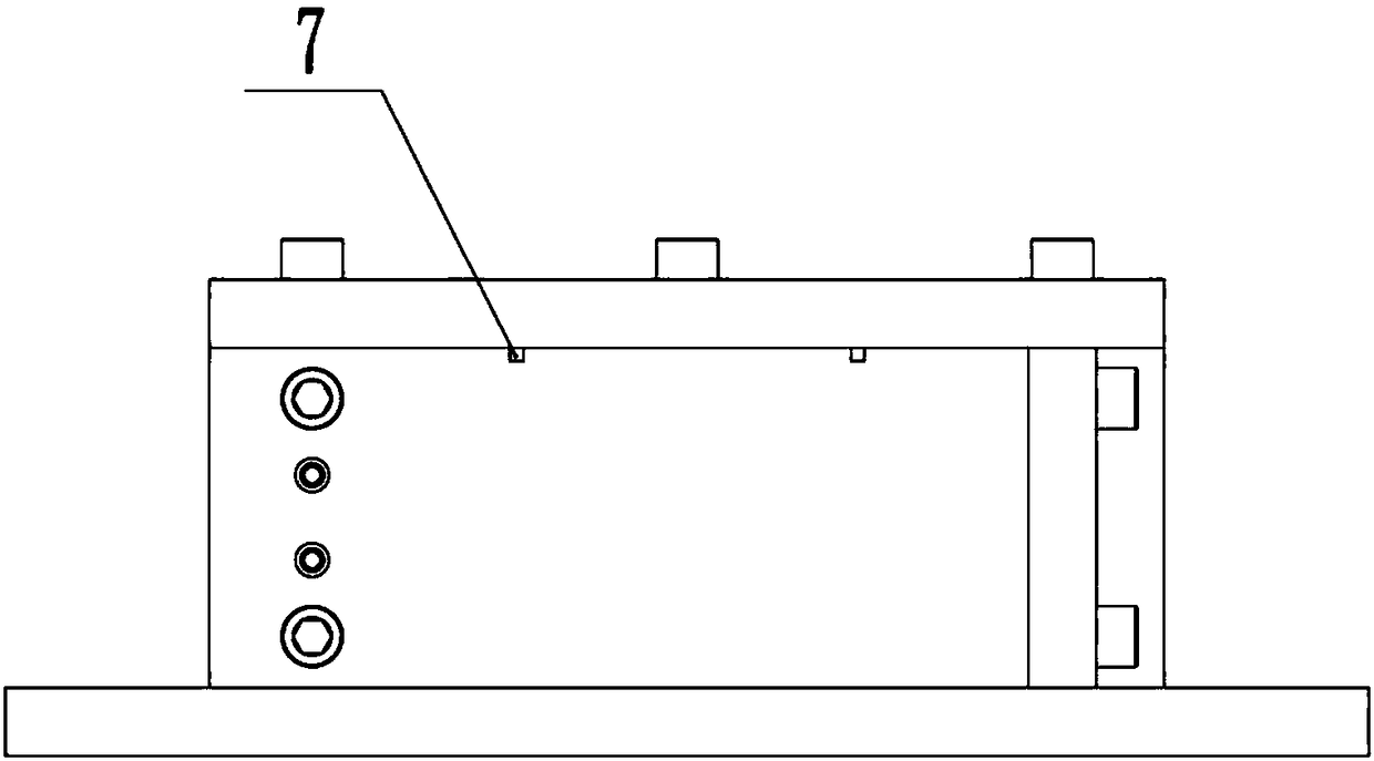
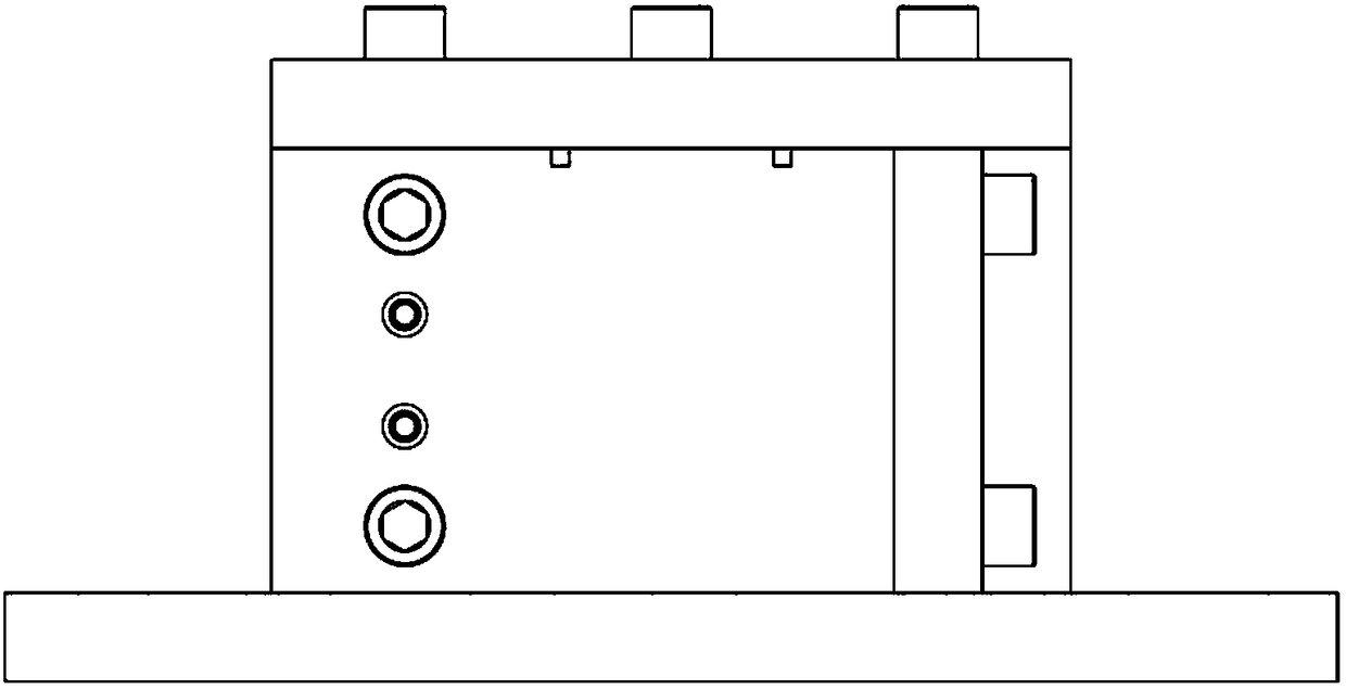
[0032] A mold for making joint specimens for shear-seepage coupling tests, such as Figure 1~4 As shown, it includes a bottom plate 1 , two short side baffles 2 , two long side baffles 3 , a cover plate 4 , screws 5 , positioning pins 6 and square slots 7 . When assembling, first fix a short side baffle 2 and a long side baffle 3 with two positioning pins 6, and then fix the other short side baffle 2 and a long side baffle 3 with two positioning pins 6 , and then place the matching joint replication silica gel plate and rectangular iron block in the cavity of the above-mentioned combined long and short boards, and then install the other four positioning pins 6 and eight screws 5 so that they are fastened as a whole, on the long and short side boards Apply a special release agent for epoxy resin mortar around the inner side of the cover and the bottom of the cover, so that you can start to make the upper half of the rock joint.

[0033] In order to pull out the positioning pin...


PUM


Abstract

The invention relates to a mold and a method for making a joint sample for shear and seepage coupling test. The mold comprises a base plate, a side enclosure body arranged on the base plate and a cover plate covering the top of the side enclosure body, the side enclosure body comprises four side baffle plates which are sequentially abutted, one end of every side baffle plate is abutted against themiddle part of the adjacent side baffle plate, the side baffle plates are fixed by screws and positioning pins, and the cover plate is fixedly connected with the tops of the four side baffle plates through screws. The material of the finally obtained joint sample is resin concrete, and the resin concrete contains epoxy resin, cement, sands, dibutyl ester and ethylenediamine according to a mass ratio of 1:(1.1-1.3):(2.0-3.0):(0.08-0.15):(0.04-0.1). The mold and the method can be used to accurately produce the rock joint sample with a required size; the joint manufacturing method has the advantages of safety and simplicity in operation, and realization of large-batch production of samples; and the produced sample has the advantages of good effect, short producing and curing period, and highjoint strength.

Description

technical field [0001] The invention relates to the technical fields of rock mechanics and seepage mechanics, in particular to a mold and a method for making a joint sample for a shear-seepage coupling test. Background technique [0002] After long-term complex geomechanical action, many joint surfaces of different scales will be formed in the rock mass. Because their strength and deformation parameters are often one or even several orders of magnitude lower than that of rock materials, they are the decisive factors for the stability of engineering rock mass. In addition, compared with the low permeability of the rock material itself, the joint surface has become the main channel for groundwater migration in rock mass engineering, especially in recent years with the deep underground rock mass engineering such as nuclear waste treatment, oil and gas storage, CO 2 In the construction of large-scale projects such as storage, the hydraulic properties of rock mass joints are one ...

Claims


Application Information

Patent Timeline
Patent Type & Authority Applications(China)
IPC IPC(8): G01N1/28
CPCG01N1/28
Inventor 夏才初钱鑫桂洋杜时贵刘育明喻强锋庄小清
Owner TONGJI UNIV
Why Eureka
Try Eureka