DDS-based aero-engine rotation speed sensor simulation device and method
A speed sensor and aero-engine technology, applied in the direction of engine testing, measuring devices, instruments, etc., can solve the problems of different output impedance, difficult program control and system integration, flexibility, compatibility and poor impedance matching, and achieve device structure Simple, easy-to-operate effects
- Summary
- Abstract
- Description
- Claims
- Application Information
AI Technical Summary
Problems solved by technology
Method used
Image
Examples
Embodiment 1
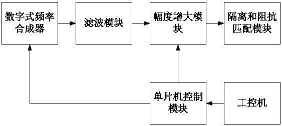
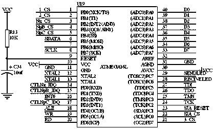
[0026] The DDS-based aeroengine speed sensor simulation device of the present embodiment, such as figure 1 and figure 2 Shown: Including industrial computer, used to give instructions on the number of revolutions; digital frequency synthesizer, used to generate the sinusoidal signal of the corresponding frequency from the number of revolutions; filter module, used to filter the sinusoidal signal to obtain the DC component Sinusoidal signal; amplitude amplification module, used to amplify the amplitude of the sinusoidal signal of the DC component to the required value; isolation and impedance matching module, used to isolate and match the amplitude-amplified signal and output it; the single-chip microcomputer control module is used for the digital The digital frequency synthesizer and the amplitude amplification module are controlled; the digital frequency synthesizer, the filter module, the amplitude amplification module, the isolation and the impedance matching module are co...
Embodiment 2
[0029] This embodiment is further optimized on the basis of embodiment 1, such as figure 2 Shown: the digital frequency synthesizer is chip AD9833. The chip AD9833 is used here as a digital frequency synthesizer because the core of the AD9833 is a 28-bit phase accumulator, which is composed of an adder and a phase register. Every time a clock comes, the phase register increases in steps, and the output of the phase register After being added with the phase control word, it is input to the address of the sine look-up table. The sine lookup table contains the digital amplitude information of a period sine wave, and each address corresponds to a phase point within the range of 0°-360° in the sine wave. The look-up table maps the input address phase information into a digital signal with a sine wave amplitude, and outputs an analog signal to the DAC. The phase register returns to the initial state after every 228 / M MCLK clocks, and the sine look-up table returns to the correspon...
Embodiment 3
[0033] This embodiment is further optimized on the basis of embodiment 2, such as figure 2 As shown: the filter module is mainly composed of a first filter capacitor and a second filter capacitor. Using two capacitors to form a filter module for filtering is simple and practical, and can effectively filter the sinusoidal signal out of the DC component.
[0034] The amplitude amplification module is mainly composed of the first operational amplifier, the second operational amplifier, the third operational amplifier, the fourth operational amplifier and chip DAC0832; the input terminal of the first operational amplifier is connected to the output of the chip AD9833 through the first filter capacitor end; the input end of the second operational amplifier is connected to the output end of the first operational amplifier, and the output end of the second operational amplifier is connected to the input end of the chip DAC0832 through the second filter capacitor; the input end of th...
PUM
 Abstract
Description
Claims
Application Information
 - R&D
- Intellectual Property
- Life Sciences
- Materials
- Tech Scout
- Unparalleled Data Quality
- Higher Quality Content
- 60% Fewer Hallucinations
Browse by: Latest US Patents, China's latest patents, Technical Efficacy Thesaurus, Application Domain, Technology Topic, Popular Technical Reports.
© 2025 PatSnap. All rights reserved.Legal|Privacy policy|Modern Slavery Act Transparency Statement|Sitemap|About US| Contact US: help@patsnap.com


