
Microcavity array coupled structure for quantum well detector and manufacturing method thereof

A technology of coupling structure and manufacturing method, which is applied in the field of semiconductor photon detectors, can solve problems such as unfavorable device integration, not much improvement in device performance, and inability to realize normal incidence of light, so as to reduce dark current, enhance electric field, and improve Effect of Operating Temperature

Pending Publication Date: 2018-08-21
SHANGHAI INST OF MICROSYSTEM & INFORMATION TECH CHINESE ACAD OF SCI
View PDF0 Cites 2 Cited by
  • Summary
  • Abstract
  • Description
  • Claims
  • Application Information

AI Technical Summary

Problems solved by technology

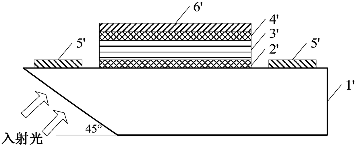
[0006] At present, the two commonly used coupling methods for THz QWPs are: 45° bevel polished substrate coupling and metal scattering grating coupling. Among them, the 45° bevel polished substrate coupling mechanism cannot achieve normal incidence of light (such as figure 1 As shown, the GaAs substrate 1' needs to be polished with a 45° bevel, and the incident light needs to be incident from the 45° bevel), which is also not conducive to device integration. Although the grating coupling can realize the normal incidence coupling of light, it does not have much effect on the device performance. big boost

Method used


Image

  • Microcavity array coupled structure for quantum well detector and manufacturing method thereof
  • Microcavity array coupled structure for quantum well detector and manufacturing method thereof
  • Microcavity array coupled structure for quantum well detector and manufacturing method thereof

Examples


Embodiment Construction

[0041] Below in conjunction with the drawings, preferred embodiments of the present invention are given and described in detail.

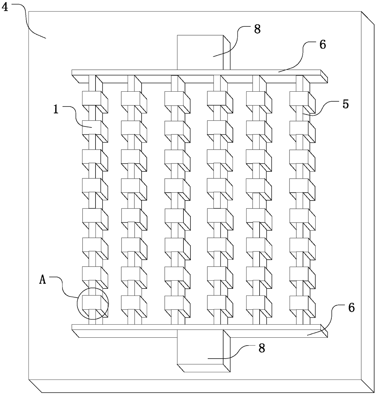
[0042] Such as Figure 2-4 As shown, one of the present invention, that is, a microcavity array coupling structure for a quantum well detector, includes: a plurality of microcavity units 1 distributed in an array and a substrate 7 located below the microcavity unit 1, wherein,

[0043] Each microcavity unit 1 comprises: upper metal electrode 2, and the epitaxial layer 3 (the geometric dimension of epitaxial layer 3 is identical with the geometric dimension of upper metal electrode 2) of the quantum well detector that is arranged on the lower surface of upper metal electrode 2 ), all microcavity units 1 also include a common lower metal electrode plate 4 on which the epitaxial layer 3 for the quantum well detector is arranged, and the lower metal electrode plate 4 is arranged on the upper surface of the substrate 7;

[0044] A plurality of microcav...


PUM


Abstract

The invention relates to a microcavity array coupled structure for a quantum well detector and a manufacturing method thereof. The coupled structure comprises multiple microcavity units distributed inan array and a substrate below the microcavity units. Each microcavity unit comprises an upper metal electrode and an epitaxial layer which is arranged in the quantum well detector on the lower surface of the upper metal electrode, and the geometric dimension of each epitaxial layer is identical to that of the corresponding upper metal electrode; all the microcavity units further comprise a shared lower metal electrode plate provided with the epitaxial layers, and the lower metal electrode plate is arranged on the upper surface of the substrate. According to the microcavity array coupled structure, normal incidence coupling of light can be achieved, the light absorption efficiency of a quantum well is effectively improved, the dark current of the quantum well detector is lowered, the working temperature of the structure is increased, the effect of enhancing an electric field in a microcavity can be achieved, and the light coupling efficiency of the quantum well detector is improved.

Description

technical field [0001] The invention relates to a semiconductor photon detector, in particular to a microcavity array coupling structure for a quantum well detector and a manufacturing method thereof. Background technique [0002] Terahertz (THz) waves generally refer to electromagnetic waves with frequencies ranging from 100 GHz to 10 THz, corresponding wavelengths in the range of 3 mm to 30 μm, and between millimeter waves and infrared light. THz wave occupies a special position in the electromagnetic spectrum, and is in the transition zone from electronics to photonics. Its long-wave end coincides with submillimeter wave, while its short-wave end overlaps with far-infrared wave. The fields of biomedicine, space exploration and global environmental detection all have very wide application potential. However, due to the lack of effective radiation sources and detectors, the research and application development of the THz band is still in its infancy. Therefore, the key to...

Claims


Application Information

Patent Timeline
IPC IPC(8): H01L31/101H01L31/0224H01L31/02H01L31/18
CPCH01L31/02H01L31/0224H01L31/101H01L31/18Y02P70/50
Inventor 张真真万文坚黎华符张龙李子平仲雨曹俊诚
Owner SHANGHAI INST OF MICROSYSTEM & INFORMATION TECH CHINESE ACAD OF SCI
Learn More