Supercharge Your Innovation With Domain-Expert AI Agents!

Assembly type temporary steel bridge structure and construction method thereof

A prefabricated, steel portable bridge technology, which is applied in basic structure engineering, erection/assembly bridges, portable bridges, etc., can solve problems such as difficulty in ensuring construction quality, damage to pipe pile structures, and easily damaged bridge decks, etc., to improve the use of Range and flexibility, protection of pile foundation structure, effect of improving load-bearing performance

Pending Publication Date: 2018-08-24
ANHUI HIGHWAY BRIDGE ENG CO LTD
View PDF9 Cites 8 Cited by
  • Summary
  • Abstract
  • Description
  • Claims
  • Application Information

AI Technical Summary

Problems solved by technology

There are many problems in this construction method. For example, the parallel bracing and scissor bracing set between the piles need to use welding to connect the supporting structure and the pile foundation as a whole, but welding will cause certain damage to the pipe pile structure, so in a certain Affects the bearing capacity and stability of the pile foundation to a certain extent
In addition, on-site construction requires a lot of welding work, and the construction period and construction quality are difficult to guarantee under the poor conditions of the water surface.
Riding bolts cannot ensure that the distribution beam and the Bailey beam are stressed at the same position, which affects the bearing performance of the Bailey beam
Traditional steel temporary bridge decks have to be laid layer by layer, and a lot of welding work is required. In addition to the problems mentioned above, it is not easy to remove the bridge deck during the demolition stage of the steel temporary bridge, and it is easy to damage the bridge deck during the demolition process

Method used


Image

  • Assembly type temporary steel bridge structure and construction method thereof
  • Assembly type temporary steel bridge structure and construction method thereof
  • Assembly type temporary steel bridge structure and construction method thereof

Examples


Embodiment Construction

[0038] The present invention will be further described below in conjunction with accompanying drawing of description, but protection scope of the present invention is not limited thereto:

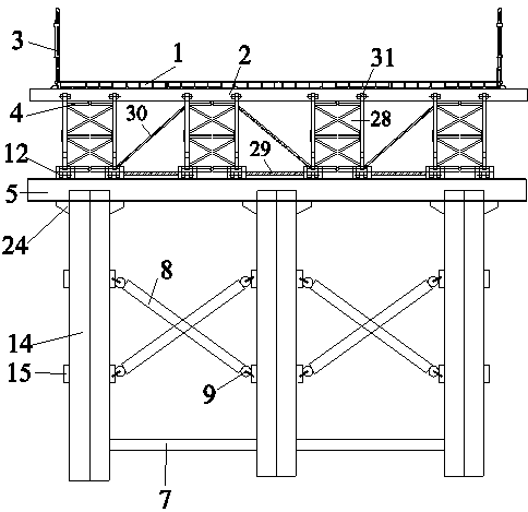
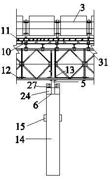
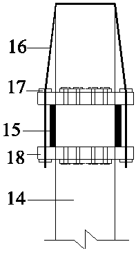
[0039] like Figure 1-9 As shown, the assembled steel temporary bridge structure of the present invention includes steel pipe pile top parallel steel corbel system, Bailey main beam and distribution beam system, assembled integral bridge deck pavement and guardrail system;

[0040] The steel pipe pile top parallel connection steel corbel system includes a unit type steel horizontal connection frame 8 arranged in the middle of the steel pipe pile 14 and located between two adjacent steel pipe piles 14, and a steel pipe pile near the top of the steel pipe pile 14 Pile top steel corbel 24, steel pipe pile through ear plate 25, corbel reinforcing ring plate 26 and corbel stiffening plate 6 are located at the bottom of steel pipe pile 14 and the pile bottom beam 7 between two adjacent steel pipe...


PUM


Abstract

The invention relates to an assembly type temporary steel bridge structure and a construction method thereof. The structure comprises three systems of the steel pipe pile top parallel connection typesteel corbel system, the bailey main beam and distributive beam system and the assembly type integral bridge deck slab laying and guardrail system. Steel pipe piles are supported through unit type profile steel parallel connection frames and pile bottom crossbeams, all of which are arranged between the piles, pile tops are provided with corbel structures and pile top load bearing beam embedded connecting grooves for installing a pile top load bearing beam, and the unit type profile steel parallel connection frames are installed through a hoop system. Bailey trusses are fixed to a bailey trussupper main beam through bailey limiting devices, and a distributive beam is installed through distributive beam containing grooves formed in the bailey truss upper main beam. The distributive beam iscovered with an assembly type integral bridge deck slab which is fixedly connected through bridge deck slab buckles finally. The novel assembly type temporary steel bridge structure can remarkably reduce field welding workload, pile foundations of the steel pipe piles are protected, the bearing performance of bailey beams is improved, construction efficiency is improved, and the construction quality is guaranteed.

Description

technical field [0001] The invention relates to a novel steel temporary bridge structure, in particular to an assembled steel temporary bridge structure and a construction method thereof. Background technique [0002] The rapid economic and social development will inevitably require a more developed transportation system. In order to meet the increasing travel needs, it is necessary to build a large number of bridges on the river. Different from the previous land construction, building bridges on water will encounter many problems whether it is material transportation, stacking or construction. Generally, steel temporary bridges are built as construction passages before bridge construction. [0003] The traditional steel temporary bridge structure is generally a steel pipe pile foundation, using welding to set up parallel braces and scissors braces, and the connection of Bailey beams using saddle bolts. There are many problems in this construction method. For example, the...

Claims


Application Information

Patent Timeline
IPC IPC(8): E01D15/12E01D19/12E01D21/00E02D5/28E01D101/30
CPCE01D15/12E01D19/125E01D21/00E02D5/285E01D2101/30
Inventor 钱申春彭申凯孙学军杜海峰刘要武任杰刘晓晗
Owner ANHUI HIGHWAY BRIDGE ENG CO LTD
Features
  • R&D
  • Intellectual Property
  • Life Sciences
  • Materials
  • Tech Scout
  • Unparalleled Data Quality
  • Higher Quality Content
  • 60% Fewer Hallucinations
Learn More