Device and system for storing mixed energy of lifting system, and control method

A hybrid energy and energy storage device technology, which is applied in the direction of circuit devices, battery circuit devices, information technology support systems, etc., can solve the problems of large investment, high operating costs, and low power efficiency of the shore crane power supply system

Active Publication Date: 2018-08-24
SHENZHEN ANSHUN ENERGY SAVING TECH DEV CO LTD
View PDF8 Cites 5 Cited by
  • Summary
  • Abstract
  • Description
  • Claims
  • Application Information

AI Technical Summary

Problems solved by technology

[0002] At present, the power system of traditional quay cranes uses a single mains power grid as power, and is composed of two large-capacity transformers to supply power to the power system and auxiliary systems. Usually, the capacity of the main transformer is ≥2500KVA, and the capacity of the auxiliary transformer is ≥250KVA. The overall power system efficiency is less than 40 %
[0003] a) Large installed capacity: Considering that the short-term peak load demand of the quay crane power system must be met, the capacity and power of the transformer must be matched according to the peak demand of the quay crane power system, which is more than twice the average power of the quay crane, resulting in the power supply system of the quay crane Large investment and high operating costs;
[0004] b) Low power efficiency: Affected by the difference in peak and valley fluctuations in energy demand during quay crane operations, the power factor of the quay crane transformer is low, resulting in low overall power

Method used


Image

  • Device and system for storing mixed energy of lifting system, and control method
  • Device and system for storing mixed energy of lifting system, and control method
  • Device and system for storing mixed energy of lifting system, and control method

Examples


Embodiment 1

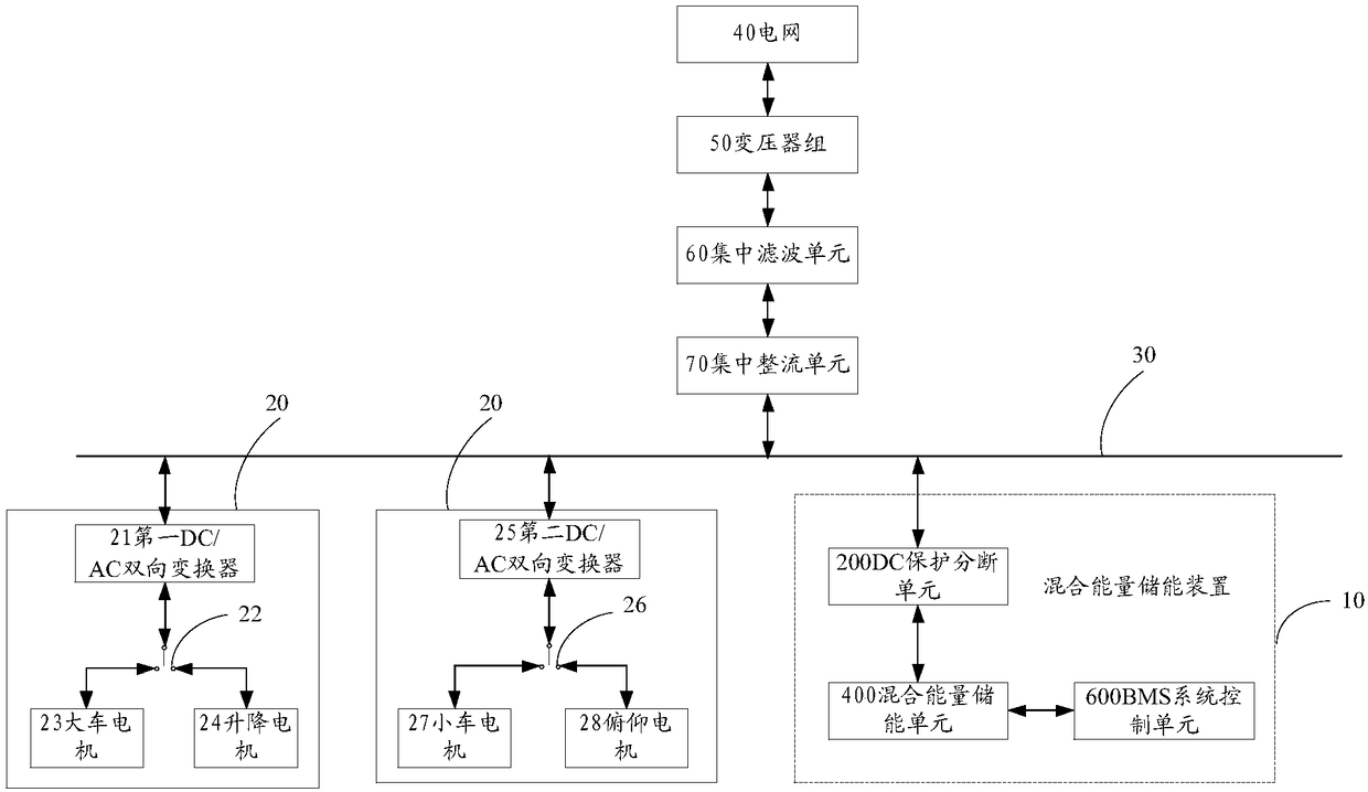
[0061] Please refer to figure 1 , figure 1 It is a module block diagram of a hybrid energy storage system according to an embodiment of the present invention. In the embodiment of the present invention, the hybrid energy storage device of the lifting system includes: a DC protection breaking unit 200, a hybrid energy storage unit 400, and a BMS system control unit 600; The protection breaking unit 200 is electrically connected to the BMS system control unit 600;

[0062] The BMS system control unit 600 controls the hybrid energy storage unit 400 to charge / discharge according to the collected voltages of the hybrid energy storage unit 400, the DC bus 30 and the power grid 40, and the hybrid energy storage unit 400 passes through the DC protection breaking unit 200 absorbs the feedback energy generated by the power system 20 electrically connected to the DC bus 30 to realize charging, or supplies power to the power system 20 connected to the DC bus 30 through the DC protection...

Embodiment 2

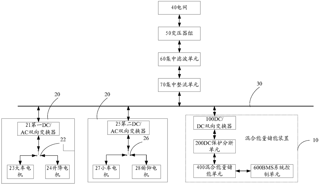
[0066] Please refer to figure 2 , figure 2 It is a module block diagram of a hybrid energy storage system according to another embodiment of the present invention. In the embodiment of the present invention, the lifting system hybrid energy storage device 10 includes: DC / DC bidirectional converter 100, DC protection breaking unit 200, hybrid energy storage unit 400 and BMS system control unit 600, the DC The / DC bidirectional converter 100 is electrically connected to the DC protection breaking unit 200, the DC protection breaking unit 200 is electrically connected to the hybrid energy storage unit 400, and the hybrid energy storage unit 400 is electrically connected to the BMS system control unit 600;

[0067] The BMS system control unit 600 controls the hybrid energy storage unit 400 to charge / discharge according to the collected voltages of the hybrid energy storage unit 400, the DC bus 30 and the power grid 40, and the hybrid energy storage unit 400 is sequentially brok...

Embodiment 3

[0076] Please refer to figure 1 and figure 2 , in an embodiment of the present invention, the hybrid energy storage system includes: a power grid 40, a transformer group 50, a centralized filter unit 60, a centralized rectification unit 70, a DC bus 30, at least one power system 20, and an energy storage device. The power grid 40 is electrically connected to the DC bus 30 through the transformer group 50, the centralized rectification unit 70 and the centralized filter unit 60 in turn, and the DC bus 30 is electrically connected to at least one power system 20 and an energy storage device respectively, and the energy storage The device is the above-mentioned lifting system hybrid energy storage device 10;

[0077] When the power system 20 generates feedback energy, the excess feedback energy is absorbed by the energy storage device electrically connected to the DC bus 30 to realize charging; The power required by the system 20 is provided by the energy storage device to rea...


PUM


Abstract

The invention discloses a device and a system for storing mixed energy of a lifting system, and a control method. The device comprises a DC protection current breaking unit, a mixed energy storing unit, and a BMS system control unit. The mixed energy storing unit is electrically connected with the DC protection current breaking unit and the BMS system control unit. The BMS system control unit controls the mixed energy storing unit to charge/discharge according to acquired voltage of the mixed energy storing unit, a DC bus, and a power grid. The mixed energy storing unit absorbs feedback energythrough the DC protection current breaking unit to realize charging, the feedback energy being generated by a power system which is electrically connected with the DC bus, or supplies power for the power system connected with the DC bus through the DC protection current breaking unit to realize discharge. The device and the system can realize double power mixed power supply, and make the power system work stably. The device and the system recycle the feedback energy fed back by the power system, and the feedback energy is recycled and used, capacity of a transformer is reduced, to achieve energy-saving effect.

Description

technical field [0001] The present invention relates to the technical field of new energy applications, in particular to a lifting system hybrid energy storage device, system and control method, which are applied to the power system of container terminal port machinery equipment, specifically rail-type shore bridge cranes, rubber tire doors Cranes and gantry cranes. Background technique [0002] At present, the power system of traditional quay cranes uses a single mains power grid as power, and consists of two large-capacity transformers to supply power to the power system and auxiliary systems. Usually, the capacity of the main transformer is ≥2500KVA, and the capacity of the auxiliary transformer is ≥250KVA. The overall power system efficiency is less than 40 %. The main reasons are as follows: [0003] a) Large installed capacity: Considering that the short-term maximum load demand of the quay crane power system must be met, the capacity and power of the transformer mus...

Claims


Application Information

Patent Timeline
IPC IPC(8): H02J7/34H02J7/00H02J3/32H02J9/06B66C13/12
CPCH02J3/32H02J7/0068H02J7/345H02J9/062B66C13/12Y04S20/20Y02B70/30
Inventor 林平安同会贾凯
Owner SHENZHEN ANSHUN ENERGY SAVING TECH DEV CO LTD
Why Eureka
Try Eureka