A Switched Reluctance Generator High Voltage DC Unit Converter System

A reluctance generator and switched reluctance technology, which is applied in the direction of controlling the generator through the change of the magnetic field, the control of the generator, the control system, etc., can solve the problems of large fluctuations in excitation power, large output voltage and current adjustment ranges, and complex structures. problem, achieve the effect of reducing the burden of rectification, stabilizing the current waveform, and enhancing flexibility

Active Publication Date: 2020-06-02
CHINA JILIANG UNIV
View PDF5 Cites 0 Cited by
  • Summary
  • Abstract
  • Description
  • Claims
  • Application Information

AI Technical Summary

Problems solved by technology

[0007] The torque ripple problem of switched reluctance motors has always been a heart problem in the industry. The torque ripple of switched reluctance generators often brings about the problem of low power quality. According to the operating principle of switched reluctance generators, the excitation If a separate excitation power supply is used in the stage, that is, a power supply that has nothing to do with the electric energy generated by the switched reluctance generator, it is beneficial to reduce the torque ripple. If you give up and use the electric energy feedback fed back by the switched reluctance generator for excitation, most of you will face the problem of large fluctuations in the supplied excitation electric energy. There are already some examples in the industry that decouple the excitation voltage from the generated voltage. For such problems, there are few advantages such as reliable isolation and adaptability to large power levels, stable output excitation voltage and current, and large output voltage and current adjustment range.
[0008] In addition, after the output of the winding converter circuit, the energy-absorbing terminal also has an impact on the torque ripple, especially when the voltage or current on the power-consuming side has periodic fluctuations, it will inevitably affect the stability of the generated voltage and current, and then through Feedback of the power supply has an impact on the excitation voltage and current, which is manifested as volatility. Therefore, when the circuit after the output of the generated voltage, such as the inverter circuit, is working, the conventional bridge inverter circuit has a greater impact on the input terminal.
[0009] After the switched reluctance generator is output by the winding converter circuit, it is often not directly connected to the DC or AC power grid, nor can it directly supply the DC or AC load. Generally, a step-up link is required. Most of the industry uses inverter first, and then power frequency or The medium and high frequency transformer boosts the voltage and rectifies it if it needs direct current. This process will affect the input side, that is, the output side of the switched reluctance generator winding converter circuit, and the generated voltage or generated current will be periodically unstable; and this type of The structure of the current conversion process is often complicated, and the control is also complicated. The high-frequency PWM mode is often used to improve the flexibility of mediation, and the switching loss of the switching tube is large and the efficiency is low.
[0010] For large-scale electricity demand, or large load, large DC power demand, etc., the electric energy generated by a single switched reluctance generator set often forms a certain power generation network with other switched reluctance generator sets, that is, multi-unit The problem of power supply after connection, which often faces high output power, that is, high voltage and high current, and the big problem faced by the switch tube in the converter system is the problem of switch stress. If the switch stress is large, it is bound to be at each switch. It requires high voltage parameters or is often a series-parallel combination mode of multiple switching tubes, which greatly increases system cost, control complexity, and loss. It often does not have practical engineering significance after facing this problem. Therefore, high-power high-voltage At the same time of supplying power, if each switch tube has low voltage stress, it is of great practical significance

Method used


Image

  • A Switched Reluctance Generator High Voltage DC Unit Converter System
  • A Switched Reluctance Generator High Voltage DC Unit Converter System
  • A Switched Reluctance Generator High Voltage DC Unit Converter System

Examples


Embodiment Construction

[0050] The switched reluctance generator of this embodiment is a four-phase winding, which is respectively M / N / P / Q four-phase windings according to the order distributed on the stator; as attached figure 1 As shown, the four-phase winding of the switched reluctance generator is connected to the winding converter circuit 1 , and the power required for the excitation stage comes from the feedback power supply 3 .

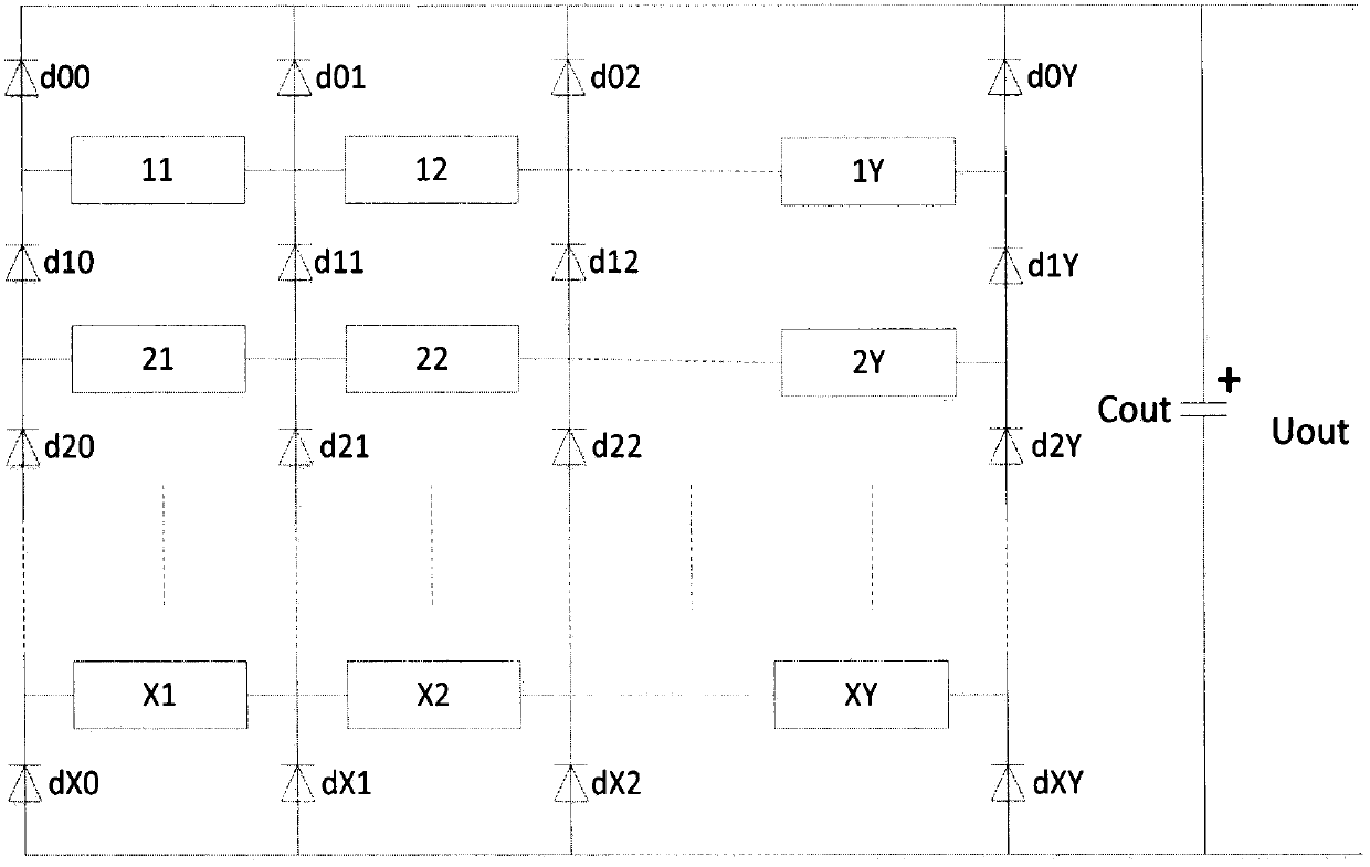
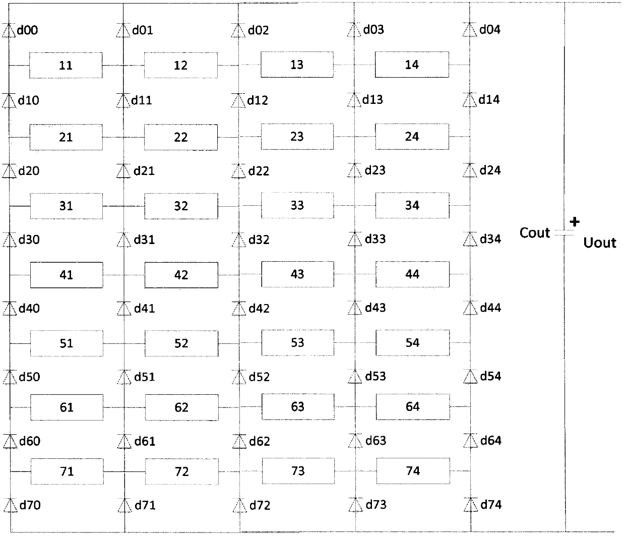
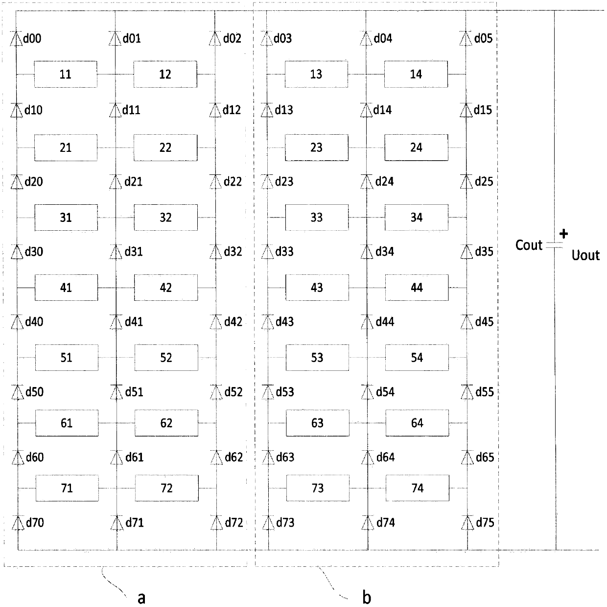
[0051] A switched reluctance generator high-voltage DC unit conversion system, which is composed of a single-switch reluctance generator unit conversion circuit and a multi-unit power convergence network, and each single-switch reluctance generator unit conversion circuit in the multi-unit power convergence network The structure of the switched reluctance generator and the inverter circuit are the same.

[0052] The converter circuit of the single-switch reluctance generator set is composed of a winding converter circuit 1, an inverter circuit 2, and a feedback power ...


PUM


Abstract

The invention relates to a high-voltage DC set conversion system of a switch reluctance power generator. The structure of the high-voltage DC set conversion system comprises a single-switch reluctancepower generator set conversion circuit and a multi-set electric energy convergence network, wherein the single-switch reluctance power generator set conversion circuit comprises a winding conversioncircuit, a feedback power supply, an inversion circuit and multi-stage boost output AC current, a switch reluctance power generator of each single-switch reluctance power generator set conversion circuit in the multi-set electric energy convergence network and the conversion circuit are same in structure, the switch reluctance power generator and a rectification diode form a multi-line multi-row DC convergence network, and a high-voltage DC current is output. The system has the advantages of high expansibility, high efficiency, high fault-tolerant performance, high reliability, simple structure and low cost and has prospect in the field of a local small-size AC-DC power grid and the like.

Description

technical field [0001] The invention relates to the field of power generation, in particular to a structure, combination, and control method of an electrical conversion system using a switched reluctance motor as a generator. Background technique [0002] The switched reluctance motor has a simple and firm structure, low manufacturing cost, no winding and no permanent magnet on the rotor, high reliability, and broad application prospects. [0003] In recent years, DC power transmission has been paid more and more attention by the power sector. The local DC power grid has begun to take shape, and more equipment has been directly powered by DC power. [0004] Switched reluctance generators generally have 2-5 phase windings placed on the stator, and the phase windings that are energized are determined according to the relative position of the salient poles between the stator and rotor. The operation of each phase winding is generally divided into two stages: excitation and powe...

Claims


Application Information

Patent Timeline
Patent Type & Authority Patents(China)
IPC IPC(8): H02P9/30
CPCH02P9/305
Inventor 孙冠群
Owner CHINA JILIANG UNIV
Why Eureka
Try Eureka