Robot welding track autonomous programming system and method based on vision sensing
A robot welding and visual sensing technology, applied in welding equipment, auxiliary welding equipment, welding/cutting auxiliary equipment, etc., can solve the problems of precision influence, difficulty in meeting efficiency and precision, etc., to improve manufacturing flexibility and avoid man-machine connection. The effect of mixing jobs and improving programming efficiency
- Summary
- Abstract
- Description
- Claims
- Application Information
AI Technical Summary
Problems solved by technology
Method used
Image
Examples
Embodiment 1
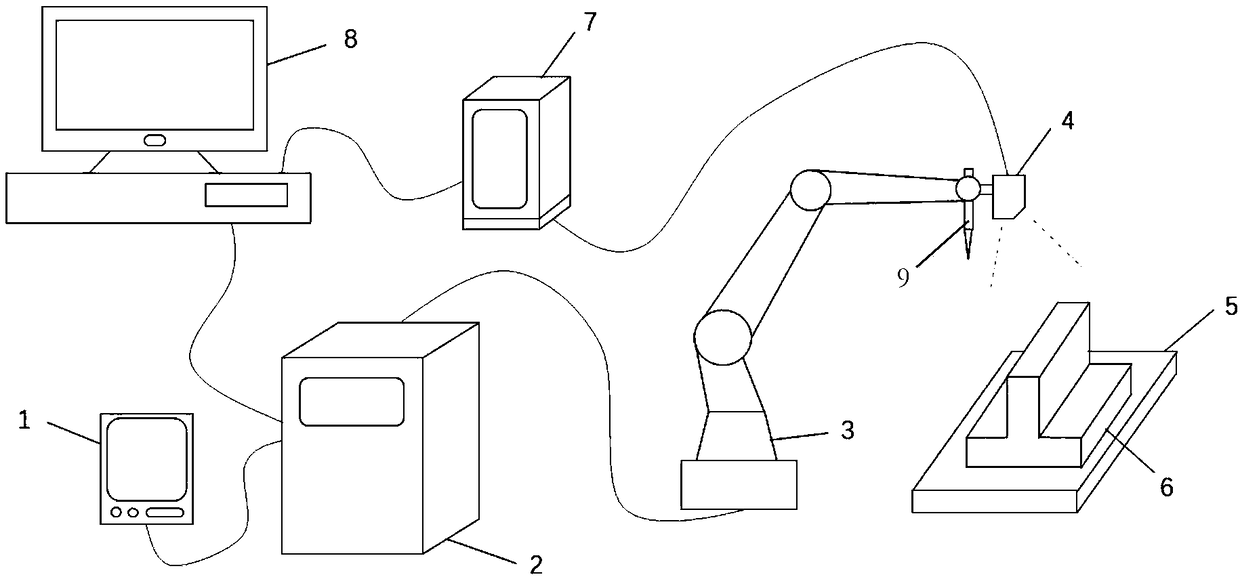
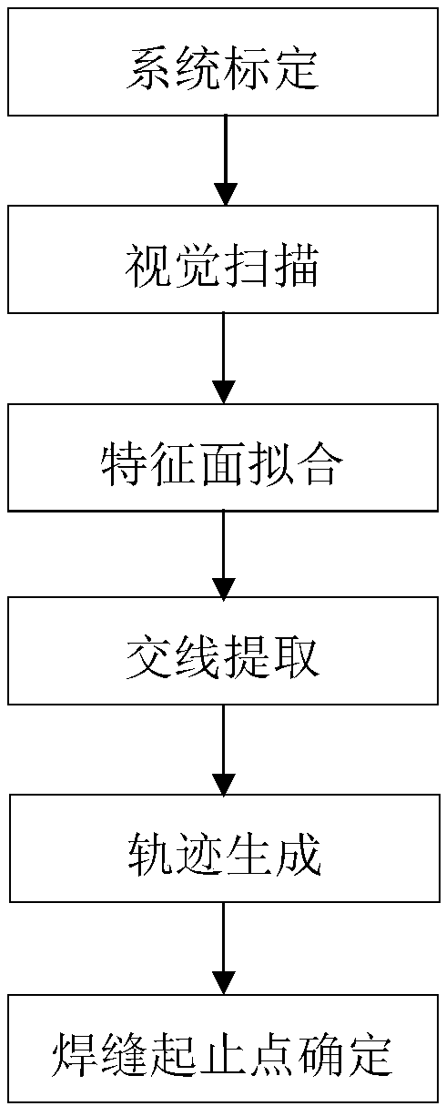
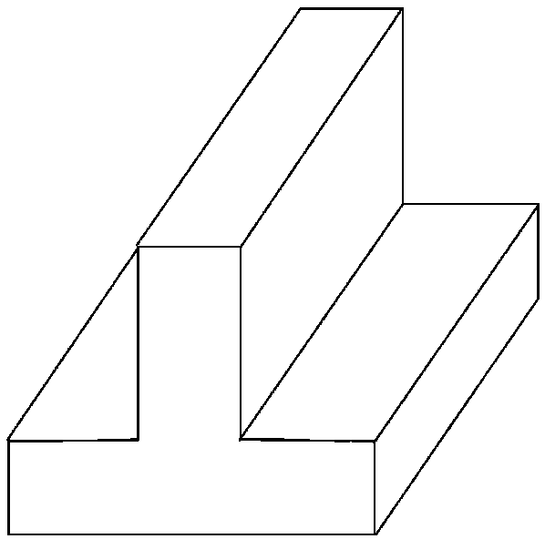
[0031] see figure 2 , image 3 and Figure 4 , an autonomous programming method of robot welding trajectory based on visual sensing is used for automatic welding of T-shaped plate fillet welds, including the following steps:
[0032] System calibration: calibrate the 3DH parameters of the industrial robot to determine the robot base coordinate system, calibrate the industrial robot end effector 9TCP to determine the robot end coordinate system, and then obtain the transformation matrix between the robot base coordinate system and the robot end coordinate system [R( δ), T(δ)] (where R is the rotation matrix, T is the translation matrix, and δ is the robot joint angle vector), and the coordinates of TCP in the end coordinate system of the robot [L x , L y , L z ]. The position coordinates of TCP in the robot base coordinate system can be calculated according to [R(δ), T(δ)]·[L x , L y , L z ,1] T calculated;
[0033] Visual scanning: According to the scanning program,...
Embodiment 2
[0039] see figure 2 , Figure 5 and Figure 6 , an autonomous programming method of robot welding trajectory based on visual sensing is used for automatic welding of 90-degree intersecting pipes, including the following steps:
[0040] System calibration: calibrate the 3DH parameters of the industrial robot to determine the robot base coordinate system, calibrate the end effector TCP of the industrial robot to determine the robot end coordinate system, and then obtain the transformation matrix between the robot base coordinate system and the robot end coordinate system [R( δ), T(δ)] (where R is the rotation matrix, T is the translation matrix, and δ is the robot joint angle vector), and the coordinates of TCP in the end coordinate system of the robot [L x , L y , L z ]. The position coordinates of TCP in the robot base coordinate system can be calculated according to [R(δ), T(δ)]·[L x , L y , L z ,1] T calculated;
[0041] Visual scanning: according to the scanning ...
PUM
 Abstract
Description
Claims
Application Information
 - R&D
- Intellectual Property
- Life Sciences
- Materials
- Tech Scout
- Unparalleled Data Quality
- Higher Quality Content
- 60% Fewer Hallucinations
Browse by: Latest US Patents, China's latest patents, Technical Efficacy Thesaurus, Application Domain, Technology Topic, Popular Technical Reports.
© 2025 PatSnap. All rights reserved.Legal|Privacy policy|Modern Slavery Act Transparency Statement|Sitemap|About US| Contact US: help@patsnap.com


