Broadband flexible radome for microwave antenna

A flexible antenna and microwave antenna technology, applied in the field of radome, can solve the problems of increasing the mixed material, increasing the weight of the antenna, and high processing cost, so as to achieve the effects of reducing fatigue loss, reducing return loss, and improving wave transmission performance

Active Publication Date: 2020-04-17
TONGYU COMM INC
View PDF10 Cites 0 Cited by
  • Summary
  • Abstract
  • Description
  • Claims
  • Application Information

AI Technical Summary

Problems solved by technology

[0010] However, microwave antennas cover multiple frequency bands. One thickness specification of the radome designed according to the wavelength cannot adapt to multiple frequency bands. If the thickness of the radome is designed according to the working wavelength, microwave antennas in different frequency bands must adopt different thickness specifications. radome
The differences in radome specifications for different frequency bands make them unsuitable for general use, which not only leads to high production costs, such as the need for multiple production lines, multiple molds, etc., but also increases the risk of mixing materials during production or assembly
[0011] Moreover, for individual low-frequency microwave antennas, if a half-wavelength dielectric thickness is used, the weight of the antenna will inevitably increase due to the influence of thickness, which will inevitably bring a bad experience to users.
[0012] In addition, the radome is formed into a concave or convex surface shape with a certain angle through the thermoforming process. The processing cost of this method is also relatively high, which is not conducive to reducing operating costs for manufacturers.

Method used


Image

  • Broadband flexible radome for microwave antenna
  • Broadband flexible radome for microwave antenna
  • Broadband flexible radome for microwave antenna

Examples


Embodiment Construction

[0040] The technical solutions of the present invention will be clearly and completely described below in conjunction with the accompanying drawings and specific embodiments. The specific content listed in the following embodiments is not limited to the technical features necessary for the technical problem to be solved by the technical solution described in the claims. Meanwhile, the enumeration is only a part of the present invention, not all of the embodiments.

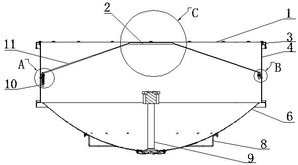
[0041] The microwave antenna broadband flexible radome of the present invention is used as an important part to protect the microwave antenna. It is arranged on the front of the antenna, fixed on the enclosure 4 around the antenna, and opposite to the reflection surface 6 of the antenna.

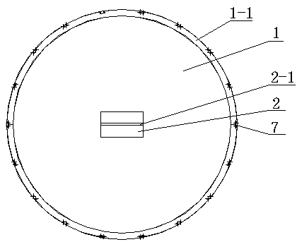
[0042]Different from rigid radomes such as common ABS engineering plastics, the radome 1 adopted by the microwave antenna in the present invention is a flexible material similar to cloth in form, and the radome 1 of this flexible...


PUM


Abstract

A microwave antenna wide-band flexible radome, its surroundings are fixed on the enclosure around the antenna, and is opposite to the reflection surface of the antenna. The fiber textile structure layer is composed of multiple layers, and the side of the radome facing the antenna reflection surface is provided with a tensioning element for connecting the traction mechanism. The traction mechanism is connected to the inner wall of the enclosure, and the radome can be turned into a The tractive force that forms the concave surface acts on the radome. The radome with this structure has good wave permeability, and it is not necessary to select the thickness of the radome according to the working wavelength of the antenna. Using a radome with a uniform thickness can obtain lower antenna insertion loss in multiple frequency bands, which can meet the use of multi-band microwave antennas. In a relatively wide frequency range, the versatility of the radome is realized, overcoming the traditional Radomes made of ABS and other materials have the disadvantage of differences due to different frequency bands.

Description

technical field [0001] The invention relates to a radome for a microwave antenna, in particular to a flexible radome for a microwave antenna that meets the requirement of wide frequency band. Background technique [0002] In the existing point-to-point communication system, the microwave antenna is an indispensable part of the system. In recent years, with the continuous development of the global microwave antenna industry, the antenna performance needs to be higher and higher. The user experience and production of microwave antenna The versatility of the system has put forward higher requirements. [0003] As an important part of the microwave antenna, the radome is installed outside the antenna and is a structure that protects the microwave antenna system from the external environment. The purpose of setting the radome mainly includes the following aspects: [0004] 1. Use the radome to establish a closed area to protect the microwave antenna system from external natural ...

Claims


Application Information

Patent Timeline
Patent Type & Authority Patents(China)
IPC IPC(8): H01Q1/42
CPCH01Q1/427H01Q19/193
Inventor 刘彬彬陈鹏羽李骁男熊国辉许超磊林泽银郭浩楠
Owner TONGYU COMM INC
Why Eureka
Try Eureka