
Cooperative control method for accessing offshore wind plant to traditional high-voltage direct current system

A high-voltage DC and cooperative control technology, applied in wind power generation, power transmission AC network, electrical components, etc., can solve problems such as difficult to achieve active power balance of sending busbars, failure to consider system dynamic process, frequency instability, etc., to reduce construction costs Cost vs. operating power consumption, the effect of avoiding frequency instability or synchronization instability problems

Active Publication Date: 2018-08-28
TSINGHUA UNIV
View PDF4 Cites 11 Cited by
  • Summary
  • Abstract
  • Description
  • Claims
  • Application Information

AI Technical Summary

Problems solved by technology

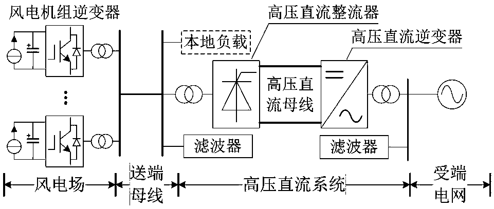
However, this scheme also has some shortcomings. First, this scheme does not consider the dynamic process of the system, especially the dynamic mutual coupling between the dynamics of the phase-locked loop in the wind turbine controller and the frequency of the bus at the sending end, which may cause frequency errors. Second, a large number of capacitive reactive power filters are hung on the sending-end busbar of the HVDC system, resulting in a coupling relationship between the sending-end busbar voltage and active power balance, and the coupling relationship between frequency and reactive power balance. It may be difficult for the rectifier to achieve the active power balance of the sending-end bus only by controlling the frequency

Method used


Image

  • Cooperative control method for accessing offshore wind plant to traditional high-voltage direct current system
  • Cooperative control method for accessing offshore wind plant to traditional high-voltage direct current system
  • Cooperative control method for accessing offshore wind plant to traditional high-voltage direct current system

Examples


Embodiment Construction

[0031] The present invention proposes a cooperative control method for connecting an offshore wind farm to a conventional high-voltage direct current system. The present invention will be described in detail below in conjunction with the accompanying drawings and embodiments.

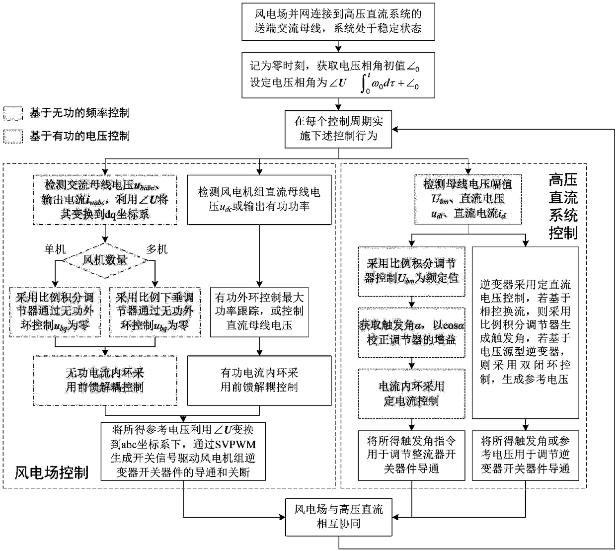
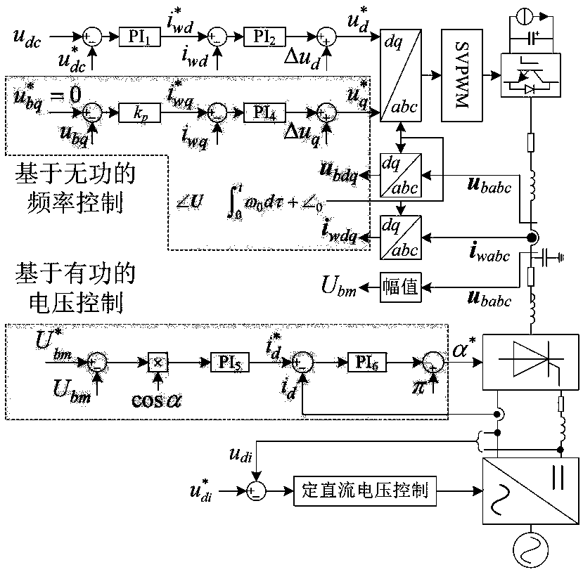
[0032] The present invention proposes a cooperative control method for connecting an offshore wind farm to a conventional high-voltage direct current system. The medium-high-voltage direct-current rectifier in the present invention is a rectifier based on phase-controlled commutation, and the high-voltage direct-current inverter can be an inverter based on phase-controlled commutation. Or based on a voltage source inverter. In the control process of this method under normal working conditions, the inverter of each wind turbine in the wind farm adopts frequency control based on reactive power, and the high-voltage DC rectifier adopts voltage control based on active power, so as to realize the wind farm an...


PUM


Abstract

The present invention provides a cooperative control method for accessing an offshore wind plant to a traditional high-voltage direct current system, belonging to the technical field of new energy generation high-voltage direct current grid connection. The method comprises the steps of: when a wind power plant is in grid connection with a sending-end alternating current bus of a high-voltage direct current system and the system is in a stable state, starting cooperative control; and when each control period is arrived, allowing the inverter of each wind turbine generator in the wind power plant employs reactive frequency control, and allowing a high-voltage direct current rectifier to employ active-based voltage control to achieve cooperative control of the wind power plant and the high-voltage direct current system. The cooperative control method can maintain voltage stability and frequency stability when the wind power plant accesses the traditional high-voltage direct current systemin a normal condition in a condition with no need for configuration of a static var compensator so as to perform real-time transmission of the maximum power captured by the wind power plant by the high-voltage direct current system, and the wind power plant can automatically perform compensation reactive power for the high-voltage direct current rectifier.

Description

technical field [0001] The invention belongs to the technical field of high-voltage direct current grid connection for new energy power generation, and in particular relates to a coordinated control method for connecting an offshore wind farm to a conventional high-voltage direct current system. Background technique [0002] In recent years, due to factors such as wind energy resources and land planning constraints, long-distance and large-capacity offshore wind farms are emerging. For the special geographical location of the offshore wind farm (hereinafter referred to as the wind farm), generally there is no high-voltage AC transmission line for transmitting the electric energy generated by the wind farm. High-voltage direct current transmission technology is widely used in long-distance large-capacity power transmission. This technology includes two typical technologies: conventional high-voltage direct current and flexible high-voltage direct current. As we all know, con...

Claims


Application Information

Patent Timeline
IPC IPC(8): H02J3/38H02J3/36
CPCH02J3/36H02J3/386Y02E10/76Y02E60/60
Inventor 耿华何秀强杨耕
Owner TSINGHUA UNIV
Learn More